


Hardware components | ||||||
_ztBMuBhMHo.jpg?auto=compress%2Cformat&w=48&h=48&fit=fill&bg=ffffff) |
| × | 1 | |||
 |
| × | 1 | |||
 |
| × | 1 | |||
 |
| × | 1 | |||
 |
| × | 1 | |||
 |
| × | 1 | |||
 |
| × | 1 | |||
 |
| × | 1 | |||
Software apps and online services | ||||||
 |
| |||||
| ||||||
| ||||||
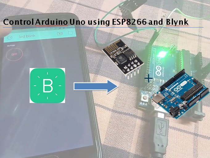
This project enables you to control the Arduino pins using ESP8266-01 WiFi module and Blynk App. Blynk App is very easy to use and is great way to begin learning about IoT.
Step 1: Gather EverythingThese are the things that you need. Make sure you have everything in a folder beforehand
1) Arduino IDE : https://www.arduino.cc/en/Main/Software
2) Blynk Libraries (latest version): https://github.com/blynkkk/blynk-library/releases
3) ESP8266 flasher tool: https://os.mbed.com/media/uploads/sschocke/esp_flasher.zip
Step 2: Installing Arduino IDE and librariesInstall the latest version of Arduino IDE.
Open Arduino IDE and go to file-> preferences-> in additional board manager URL type - http://arduino.esp8266.com/stable/package_esp8266com_index.json
Go to tools -> boards -> Board Manager --> and install the esp8266 package found at last. (optional)
Extract the blynk library zip file and copy the contents inside library folder in the zip file into -
user documents--> Arduino --> Libraries
Step 3: Flashing ESP8266 FirmwareYou need to make the circuit shown below in order to flash the firmware onto the ESP8266:
In many forums I have read that the esp8266 can be flashed without using FTDI usb to ttl converter. Instead many people have used Arduino UNO to flash the esp8266. However from my personal experience it is better to buy a FTDI USB to TTL converter/Cable as the arduino thing didn't work for me( may be because of power issue).
Extract the esp_flasher.zip and run the application XTCOM_UTIL.
Connect the Esp8266-01 to the computer through the circuit. You need to know the right COM port which is used for communication. go to device manager and Click on ports(COM & LPT). Then note down the COM port used by the ESP8266-01.
In XTCOM_UTIL go to tools-->Config Device and select the right com port and baud rate as 9600. Click on Open. Then if the operation is Successful click on Connect. then Esp8266 will be Connected. If you encounter an error then unplug the cable and insert it again.
Inside the esp_flasher.zip file, you will find a readme.txt file containing the addresses to which each of the .bin files to be flashed.
go to API Test-->flash Image download. browse the correct.bin file and enter the address corresponding the bin file and click on download.
for example: boot_v1.1.bin---------------->0x00000
after the operation is successful close the XTCOM_UTIL and also unplug ESP8266( this must be done in between the flashing of each.bin file). Again reopen XTCOM_UTIL and plug Esp8266 and repeat the above steps to flash all the 4 bin files at their correct address.
(remember to ground the GPIO0 at all time during flashing)
For detailed instruction, please refer to this: https://os.mbed.com/users/sschocke/code/WiFiLamp/wiki/Updating-ESP8266-Firmware
Step 4: AT CommandTo enter AT commands go to arduino IDE while esp8266 is still connected. just select the right port in tools ( no need to bother about the board).
Select the baud rate as 115200 and enter the required AT commands.
Try sending the basic command : AT
You must get a OK response.
change the mode to Station mode by sending the command: AT+CWMODE=1
Step 5 : Blynk App SetupDownload the Blynk App from Play Store and Sign In.
To Create a New Project Press + icon on the top.
Give You Project Name.
Choose Device as Arduino UNO
Connection Type as WiFi and press Create.
As soon as you Create an Auth Token will be sent to your Registered e-Mail.
You Can Also send it Later in you Project Setting Page(nut Symbol)--> Devices.
To add a button press + and select Button.
Press on the newly created button to edit it.
Give it a name and set pin to digital D13.
Toggle the mode to SWITCH.
This will turn ON/OFF the IN-Built LED on the Arduino.
To control other Pins, Select the Required Pin(D3, D4... etc) in Edit Menu.
Step 6: ProgramOpen Arduino IDE.
Select board to Arduino Uno and select the right port.
COPY AND PASTE THE BELOW CODE IN Adruino IDE:
/*************************************************************
 Download latest Blynk library here:
   https://github.com/blynkkk/blynk-library/releases/latest
 Blynk is a platform with iOS and Android apps to control
 Arduino, Raspberry Pi and the likes over the Internet.
 You can easily build graphic interfaces for all your
 projects by simply dragging and dropping widgets.
   Downloads, docs, tutorials: http://www.blynk.cc
   Sketch generator:           http://examples.blynk.cc
   Blynk community:            http://community.blynk.cc
   Follow us:                  http://www.fb.com/blynkapp
                               http://twitter.com/blynk_app
 Blynk library is licensed under MIT license
 This example code is in public domain.
*************************************************************
 This example shows how to use ESP8266 Shield (with AT commands)
 to connect your project to Blynk.
 WARNING!
   It's very tricky to get it working. Please read this article:
   http://help.blynk.cc/hardware-and-libraries/arduino/esp8266-with-at-firmware
 Change WiFi ssid, pass, and Blynk auth token to run :)
 Feel free to apply it to any other example. It's simple!
*************************************************************/
/* Comment this out to disable prints and save space */
#define BLYNK_PRINT Serial
#include <ESP8266_Lib.h>
#include <BlynkSimpleShieldEsp8266.h>
// You should get Auth Token in the Blynk App.
// Go to the Project Settings (nut icon).
char auth[] = "yourAUTH";
// Your WiFi credentials.
// Set password to "" for open networks.
char ssid[] = "yourSSID";
char pass[] = "yourpassword";
// Hardware Serial on Mega, Leonardo, Micro...
//#define EspSerial Serial1
// or Software Serial on Uno, Nano...
//#include <SoftwareSerial.h>
//SoftwareSerial EspSerial(2, 3); // RX, TX
// Your ESP8266 baud rate:
#define ESP8266_BAUD 115200
ESP8266 wifi(&Serial);
void setup()
{
 // Debug console
 Serial.begin(9600);
 delay(10);
 // Set ESP8266 baud rate
 Serial.begin(ESP8266_BAUD);
 delay(10);
 Blynk.begin(auth, wifi, ssid, pass);
}
void loop()
{
 Blynk.run();
}
This is the modification of Esp8266_Shield Example Program.
Replace yourAUTH with the Auth token sent to your Mail. Replace youSSID with your WiFi name and replace YourPassword with WiFi Password.
Hardware serial part is commented as we are using Arduino UNO.
**In the programI have Commented Software Serial(if using Arduino Uno). I recommend you to comment the Software Serial as its unstable. AlsoI have changed
ESP8266 wifi(&EspSerial); to ESP8266 wifi(&Serial);
and
EspSerial.begin(ESP8266_BAUD); to Serial.begin(ESP8266_BAUD);
Upload the above program to the Arduino Uno board.
After its Uploaded unplug the arduino from Computer. Now you need to connect the ESP8266 to Arduino UNO.
STEP 7: Circuit SetupESP8266 Arduino
TX -------------> Rx
Rx ------------> Tx
Gnd ------------> Gnd
Vcc -------------> 3.3v
CH_PD --------------> 3.3v
After the connection is complete, plug the Arduino into the computer.
Open the Serial Monitor and set baud rate to 115200.
You will see something like this:
In the Blynk App, select your project and click the play button.
Press the button to switch ON/OFF the LED.
Now with this the project is finished.
Hope you enjoyed the tutorial.
If you have any questions/ suggestions pls leave it in the comment section below.
Thank you!


_3u05Tpwasz.png?auto=compress%2Cformat&w=40&h=40&fit=fillmax&bg=fff&dpr=2)
Comments