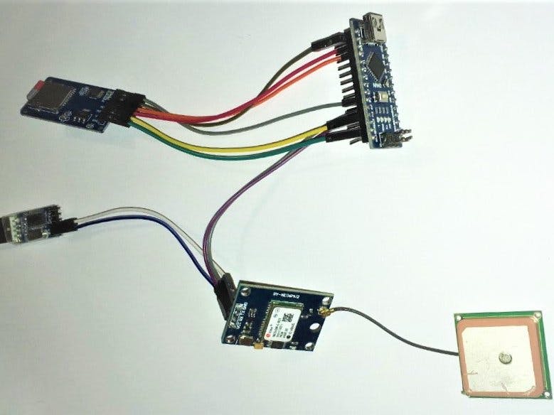
If you always wanted a DIY GPS tracker system with a low budget stay tuned to find out an easy way to implement it! The following tutorial shows how you can accomplish it!
The basic idea is to use a low budget but reliable GPS-Module that can talk to the arduino with ready-to-run software and an SD card module that stores the gps data in a file. As a result you can drive/walk/cycle anywhere you like and record your route! In the next few chapters I will get deeper to the details, tips and tricks that ensure perfect functionality!
Step 1: ComponentsThe electronic components you will need for this project are:
- Arduino Nano Board
- GPS Neo-6m Module
- SD Card Module with SPI interface
- SD Card
- USB to TTL converter (If you power it from your computer)
- Jumper Wires for the connections
Arduino Nano Board:
You can use any arduino board you like (be carefull of the pinout!!) that is arduino compatible, but I would recomend a genuine Arduino Nano board as it works best for the application. The pinout of the Arduino Nano can be seen below:
In this project we are going to use Pins: D11, D12, D13, D2, D3, D4, VCC, GND
The pins D11, D12, D13, D4 will be used for the SPI interface so that the arduino can communicate with the SD card module. The pins D2, D3 will be connected to the RX, TX pins of the GPS module to receive the location data.
GPS Neo-6m Module:
This component is a GPS module that works with 5V voltage input and it is compatible with arduino boards. This module picks up the signal of the GPS satellites that orbit above its position and by using mathematical Trilateration and presice timing it can calculate reliably its 3D position. As you can see in the above image the module is consisted by the antenna and the pcb with the chip that executes the calculations. The board also includes an EEPROM and a 3.3V regulator in order to accept 5V power from the arduino.In the following picture you can see its pinout:
Micro SD Card Module:
The micro SD module through the SPI communication protocol and it communicates with the arduino. By utilizing the SD.h library which is built-in on the arduino IDE, enables a quick and easy communication with the module. It also has a 5V to 3.3V logic converter beacuse the SD card has a 3.3V logic.Below you can see its pinout:
Micro SD Card:
Using the micro SD card module you can pretty much Read/Write data to any SD card you like! The only thing you have to pay attention to is the filing system on the SD card. The arduino can communicate with SD cards with filing system FAT 16 or FAT32. So in order to be safe you should check your SD card's specifications on your computer. If you do not find a FAT 16 or FAT 32 filing system you can download a SD card formatting software that installs a FAT 32 filing System. After you have downloaded the software you insert the SD card to the computer and by opening the software you choose the option format as you can see below:
In order to ensure that the GPS data logger code will run bug-free you can upload to the arduino the example CardInfo sketch that is built-in to the Arduino IDE.
If the system recognizes the SD card you will get its information displayed in the Serial Monitor, else it will warn that the correct filing system was not found.
USB to TTL:
Powering your project with a 9V battery is sufficient for both th GPS and the SD card modules. If you try to power up the project only by the computer USB port it will most likely not work. In this case I would suggest to use the USB to TTL converter plugged in your computer and powering up by its 5V and GND pins the GPS Module. The arduino and the SD card module will be powered by the USB cable connected to the Arduino.
Wiring connections between arduino and SD card module:
- MOSI ==> D11
- MISO ==> D12
- CLK ==> D13
- CS ==> D4
- VCC ==> 5V
- GND ==> GND
Wiring connections between arduino and Gps Neo-6m module:
- VCC ==> 5V (Arduino or TTL if powered by computer)
- GND ==> GND (Arduino or TTL if powered by computer)
- RX ==> D2
- TX ==> D3
If you power your project via your computer you should remember to use the TTL power pins!! More details in the fritzing schematic!!
The code for receiving the data from the gps module and sending them to the SD card is ready to run! You will also need to download the TinyGPS++ library from the provided link in order to receive the gps data easily!!
When you connect the project to the power supply it will take some time till the GPS module locks its 3D position so be patient!! After the position is locked it will start writing the data to SD card (Altitude, Latittude, Longtitude, Time). Every time you turn it off and then on again it will write the new data below the previous, so no data is lost!!


_FEG68hd504.png)

Comments
Please log in or sign up to comment.