


Hardware components | ||||||
_ztBMuBhMHo.jpg?auto=compress%2Cformat&w=48&h=48&fit=fill&bg=ffffff) |
| × | 1 | |||
 |
| × | 1 | |||
 |
| × | 1 | |||
 |
| × | 1 | |||
 |
| × | 1 | |||
 |
| × | 1 | |||
Software apps and online services | ||||||
 |
| |||||
Below is a video that goes through all the steps to assembling and running the Arduino Potentiometer Value Display on LCD 16x2 Look the Demonstration video HERE
IntroductionIn this project I am going to demonstrate how to Control LED through LDR.
This project will involve using a little a bit of code and a very simple circuit that’s great for beginners.The video further down this page will go through all the steps to completing this very cool Arduino DIY LED Control with LDR Sensor (Photoresistor)
This project aims to show how to control appliances when darkness appear like smart bulb.
This will serve as a base to build more amazing projects.In every electronic project we must think about what the input and output devices to use, the LDR is one of the best known and cheapest, we use the analog input reading due to the interaction of the project with the environment, along with this We must give importance to the output or presentation of the value
Working on BasicsThe LDR and LED have been powered by Arduino UNO (Board). It contains a code which uploaded to the board. And once it simulated you can see When LDR catches darkness it will send input to Board and board will pass power to the LED.
We will use an Blue LED in this tutorial and we will need one LDR, to get readings.
The Arduino uses an analog pin to read the sensor values. So the potentiometer we want to read will connect it to the analog pin of the Arduino.
Refer to this video there is full instruction CLICK HERE
There is Multiple Usage of this Product:-
- You can came to know how to interface with LDR
- If you are a beginner than this is very useful for them to get interface with Input/Output Devices
- You can check the Darkness Level value of LDR on Serial Monitor.
- You can control many Appliances.
- You can build up Many Smart Appliances for daily routine like Smart Bulb for the time when Darkness appear to start glowing automatically
Connection of LED
- Connect to Long Pin (+5V Pin) of LED to (Pin 12) of Arduino
- Connect to Small Pin (GND Pin) of LED to (GND) of Arduino
Connection of LDR
- Connect LDR (Any One Pin) to (+5V) Of Arduino
- Connect 1K Resistor to Another Pin OF LDR and Connect Resistor Pin to GND of Arduino
- Connect Ldr 2 Pin To A0 Of Arduino
Basically when there is darkness the led will glow and when there is sufficient light led will stop glowing. This a simple circuit for of interface Arduino uno with LDR sensor.
First of all we need to knw what is LDR sensor and how it works ?
LDR ( light dependent resistor ) also called photoresistors are responsive to light. Photoresistors are used to indicate the intensity or the presence or the absence of light. When there is darkness the resistance of photoresistor increases and when there is sufficient light it dramatically decreases.
LDR ( light dependent resistor ) which has two terminals. Terminal one is the signal pin which should be connected according to the code. Another terminal is considered as the ground pin which should be connected to the ground of the system.
In the simplest terms, a light-emitting diode (LED) is a semiconductor device that emits light when an electric current is passed through it. Light is produced when the particles that carry the current (known as electrons and holes) combine together within the semiconductor material. Led has two terminals : positive and negative.
Watch the Demonstration VideoComplete Video
Shorts
CLICKHERE
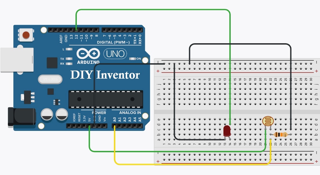
Circuit Diagram
Connect to Long Pin (+5V Pin) of LED to (Pin 12) of Arduino
Connect to Small Pin (GND Pin) of LED to (GND) of Arduino
Connection of LDR
Connect LDR (Any One Pin) to (+5V) Of Arduino
Connect 1K Resistor to Another Pin OF LDR and Connect Resistor Pin to GND of Arduino
Connect Ldr 2 Pin To A0 Of Arduino


Comments
Please log in or sign up to comment.