


Hardware components | ||||||
_ztBMuBhMHo.jpg?auto=compress%2Cformat&w=48&h=48&fit=fill&bg=ffffff) |
| × | 1 | |||
 |
| × | 1 | |||
 |
| × | 1 | |||
 |
| × | 1 | |||
 |
| × | 1 | |||
 |
| × | 1 | |||
 |
| × | 1 | |||
 |
| × | 1 | |||
Software apps and online services | ||||||
 |
| |||||
Hand tools and fabrication machines | ||||||
| ||||||
Below is a video that goes through all the steps to assembling and running the traffic lights using the Arduino Look the Demonstration video HERE
IntroductionIn this project I will Demonstrate you how to make a very simple and very cool traffic light Using Arduino with LCD which shows counter for Traffic Light.
This project will involve using a little a bit of code and a very simple circuit that’s great for beginners.
The video further down this page will go through all the steps to completing this cool traffic light project.
This simple little project uses an Arduino and some LEDs to replicate a traffic light. It uses code as an internal timer and continues to run until you cut the Arduino's power supply.
This is a miniature copy of a original Traffic light. I meant to say that like Traffic light have LCD which shows Time Left and LED same I am trying to demonstrating here.
Working on BasicsThe LED have been powered by Arduino UNO (Board). It contains a code which uploaded to the board. And once it simulated LED Start's blinking like a traffic light. In this 15 Second will for Red Light 6 Second for Yellow Light (In my Project Blue) and 20 Second for Green Light.
Once code have been uploaded you will be able to see that start Displaying text like stop on red start on Yellow and go on green.
Including this you will also able to see time left for the next signal.
UsageThere is multiple usage of the project:-
- If you are beginner so it is a intro to arduino
- You can Make a real but small Traffic Light using it
- You can also add more LED and Can change as per your use
- You will learn how LCD used
Follow the Steps:-
Connection of LED
- Hook the GND pin (Negative Pin) of all led to Pin GND of Arduino.
- Connect Red LED VCC Pin (Positive Pin) to Pin 9 of Arduino.
- Connect Yellow LED VCC Pin (Positive Pin) to Pin 8 of Arduino.
- Connect Green LED VCC Pin (Positive Pin) to Pin 7 of Arduino.
Connection of LCD
- Connect the First pin from the left of LCD (GND pin) with GNDpin of Arduino.
- Connect the Second pin from the left of LCD (VCC pin) with VCCpin of Arduino.
- Connect the Third pin from the left of LCD (V0 pin) with GNDpin of Arduino.
- Connect the Fourth pin from the left of LCD (RS pin) with 11pin of Arduino.
- Connect the Fifth pin from the left of LCD (R/W pin) with GNDpin of Arduino.
- Connect the Sixth pin from the left of LCD (E pin) with 10pin of Arduino.
- Connect the Eleventh pin from the left of LCD (D4 pin) with 5pin of Arduino.
- Connect the Twelveth pin from the left of LCD (D5 pin) with 4pin of Arduino.
- Connect the Thirteen pin from the left of LCD (D6 pin) with 3pin of Arduino.
- Connect the Fourteenth pin from the left of LCD (D7 pin) with 2pin of Arduino.
- Connect the Fifteenth pin from the left of LCD (5V pin) with 1 K Resistor with 2pin of Arduino.
- Connect the Last pin from the left of LCD (GND pin) with GND pin of Arduino.
Remember to install LiquidCrystal.h library from HERE
- Copy or download the code attached with the project.
- Hit upload and look into LCD.
- Hit upload and look into LED's too.
- You will able to see the Red LED will on for 15 second and then yellow led (mine Blue) will blink for 6 sec and then green led will constant on for 20 sec and then it again repeat the process
- You will also able to see that on LCD time left will be shown how much time left for next signal and the action to be done on the signal like Stop, Start, Go
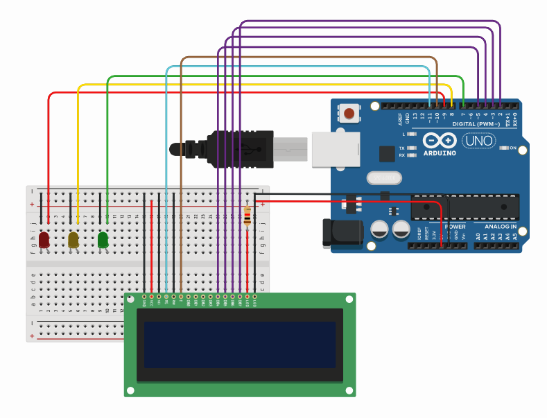
Circuit Diagram
Hook the GND pin (Negative Pin) of all led to Pin GND of Arduino.
Connect Red LED VCC Pin (Positive Pin) to Pin 9 of Arduino.
Connect Yellow LED VCC Pin (Positive Pin) to Pin 8 of Arduino.
Connect Green LED VCC Pin (Positive Pin) to Pin 7 of Arduino.
Connection of LCD
Connect the First pin from the left of LCD (GND pin) with GNDpin of Arduino.
Connect the Second pin from the left of LCD (VCC pin) with VCCpin of Arduino.
Connect the Third pin from the left of LCD (V0 pin) with GNDpin of Arduino.
Connect the Fourth pin from the left of LCD (RS pin) with 11pin of Arduino.
Connect the Fifth pin from the left of LCD (R/W pin) with GNDpin of Arduino.
Connect the Sixth pin from the left of LCD (E pin) with 10pin of Arduino.
Connect the Eleventh pin from the left of LCD (D4 pin) with 5pin of Arduino.
Connect the Twelveth pin from the left of LCD (D5 pin) with 4pin of Arduino.
Connect the Thirteen pin from the left of LCD (D6 pin) with 3pin of Arduino.
Connect the Fourteenth pin from the left of LCD (D7 pin) with 2pin of Arduino.
Connect the Fifteenth pin from the left of LCD (5V pin) with 1 K Resistor with 2pin of Arduino.
Connect the Last pin from the left of LCD (GND pin) with GND pin of Arduino.

Comments