After this tutorial, you are able to display the current time and date from your Arduino to an LCD display. And with the press of a button, the temperature and humidity are shown. This project is intended for beginners and also explains how to set up all of the components.
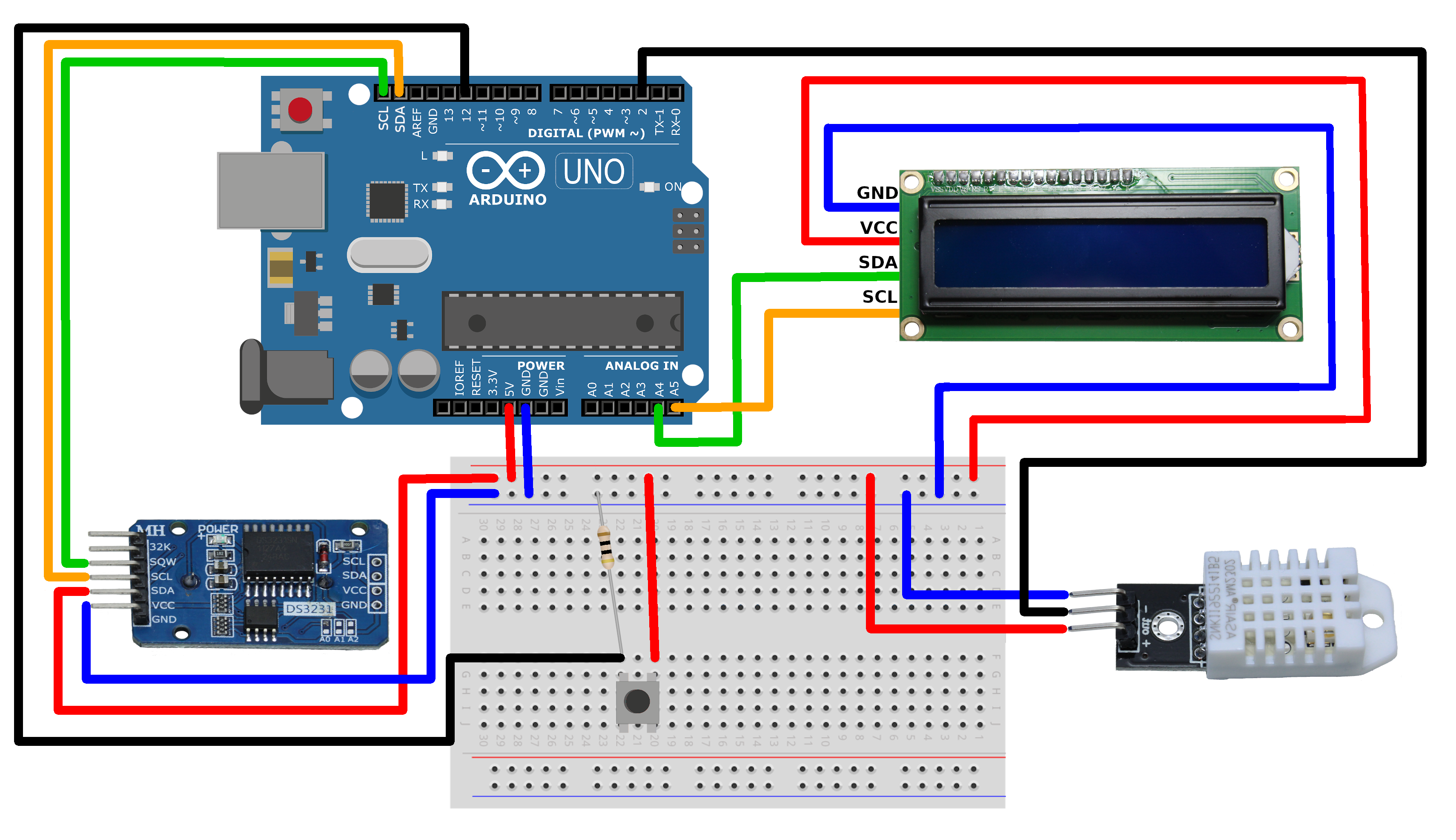
If you want to start directly, jump to the end where you will find the code, as well as the schematic on how to connect all of the parts.
HardwareTo follow this project, you will need the following components:
- Arduino Uno
- DHT22 sensor
- 16x2 LCD with pre-soldered i2c-controller
- RTC DS3231 module
- 10 kOhm resistor
- a button
- breadboard
- jumper wires
- USB-A to B cable
You need to install the Arduino IDE found here: https://www.arduino.cc/en/Main/Software
When you first connect your Arduino, you will be automatically prompted to install the required drivers.
Then, install the following libraries from the library manager inside the Arduino IDE:
- Adafruit Unified Sensor
- DHT sensor library
- LiquidCrystal I2C
Guidance on how to install libraries can be found here: https://www.arduino.cc/en/Guide/Libraries
Find out the hardware address of the LCDTo use the LCD for displaying your information, it is needed to find out its hardware address. To do that, connect the pins of the LCD to the Arduino like that:
- VCC -> 5V
- GND -> GND
- SDA -> A4
- SCL -> A5
Now that the display is connected, it won't take long and you will have its address. To identify it, open up the Arduino IDE and paste the following code there. Then click on 'upload'.
#include <Wire.h>
void setup() {
Serial.begin (115200);
// Leonardo: wait for serial port to connect
while (!Serial)
{
}
Serial.println ();
Serial.println ("I2C scanner. Scanning ...");
byte count = 0;
Wire.begin();
for (byte i = 8; i < 120; i++)
{
Wire.beginTransmission (i);
if (Wire.endTransmission () == 0)
{
Serial.print ("Found address: ");
Serial.print (i, DEC);
Serial.print (" (0x");
Serial.print (i, HEX);
Serial.println (")");
count++;
delay (1); // maybe unneeded?
} // end of good response
} // end of for loop
Serial.println ("Done.");
Serial.print ("Found ");
Serial.print (count, DEC);
Serial.println (" device(s).");
} // end of setup
void loop() {}
Now open the serial monitor as shown below:
Make sure that the baud rate is set to 115200 in the right corner. Then you should see an output similar to this:
In my case, it found 3 devices, but if you only connected the LCD before, the only shown address is the one from your LCD (in my case it is 0x27). Note that address because we will need it later.
Set up the RTC-ModuleYou will need an additional library to work with the RTC-module. I used the library from here: http://www.rinkydinkelectronics.com/library.php?id=73
Download the file named DS3231.zip and import it inside the IDE. A guide for importing libraries can be found here: https://www.arduino.cc/en/Guide/Libraries
First, connect the pins of the clock-module to the following pins of the Arduino:
- VCC -> 5V
- GND -> GND
- SDA -> SDA
- SCL -> SCL
- SQW -> unused
- 32K -> unused
The following code gives you the ability to initially set the time of the clock.
#include <DS3231.h>
// Init the DS3231 using the hardware interface
DS3231  rtc(SDA, SCL);
void setup()
{
 // Setup Serial connection
 Serial.begin(115200);
 // Uncomment the next line if you are using an Arduino Leonardo
 //while (!Serial) {}
 // Initialize the rtc object
 rtc.begin();
 // The following lines can be uncommented to set the date and time
 rtc.setDOW(FRIDAY);     // Set Day-of-Week to SUNDAY
 rtc.setTime(12, 00, 0);     // Set the time to 12:00:00 (24hr format)
 rtc.setDate(1, 5, 2020);   // Set the date to May 1st, 2020
}
void loop()
{
 // Send Day-of-Week
 Serial.print(rtc.getDOWStr());
 Serial.print(" ");
 // Send date
 Serial.print(rtc.getDateStr());
 Serial.print(" -- ");
 // Send time
 Serial.println(rtc.getTimeStr());
 // Wait one second before repeating :)
 delay (1000);
}
Copy it inside the Arduino IDE. Then insert your current time and date into lines 13 - 15 as explained in the comments there. Now upload the code to your Arduino and the time is set. After you've done that, comment these three lines and upload the code again, to make sure that the set time won't get overwritten. Now you can open the serial monitor and should be able to see an output similar to this one:
Now the time has come to get some results and therefore we will assemble all of the parts together. The schematic at the end shows exactly, where you have to put all of the wires. When you've done that, copy the code found at the end inside the IDE and insert the hardware address of the LCD into the following line of the code (0x27 is replaced by your address):
LiquidCrystal_I2C lcd(0x27,16,2); // Init the display as "lcd"
Now it is time to upload the code found below and enjoy the project you just completed. To make it look a bit nicer, I build a case out of lego bricks for my system. So feel free to stay creative and modify this project as you want to.


_ztBMuBhMHo.jpg?auto=compress%2Cformat&w=48&h=48&fit=fill&bg=ffffff)


Comments
Please log in or sign up to comment.