Hey, what's up, Guys! Akarsh here from CETech.
Seven Segment Displays are good to look at and are always a handy tool to display data in the form of digits but there is a drawback in them which is that when we control a Seven Segment Display in reality we are controlling 8 different LEDs and to control each of them we require different outputs but if we use a separate GPIO pin for each of the LEDs on seven segment display we might face a shortage of Pins on our microcontroller and ultimately we will be left with no place to do other important connections. This may seem to you as a big problem but the solution to this problem is very simple. We just need to use the 74HC595 Shift register IC. A single 74HC595 IC can be used to provide outputs to 8 different points apart from that we can also connect a number of these ICs and use them to control a large number of devices that too by consuming just 3 GPIO pins of your microcontroller.
So in this project, we will use a 74HC595 Shift register IC with Arduino to control a Seven Segment display just by using 3 GPIO pins of the Arduino and understand how can this IC prove to be a great tool.
Get PCBs for Your Projects ManufacturedYou must check out PCBWAY for ordering PCBs online for cheap!
You get 10 good quality PCBs manufactured and shipped to your doorstep for cheap. You will also get a discount on shipping on your first order. Upload your Gerber files onto PCBWAY to get them manufactured with good quality and quick turnaround time. Check out their online Gerber viewer function. With reward points, you can get free stuff from their gift shop.
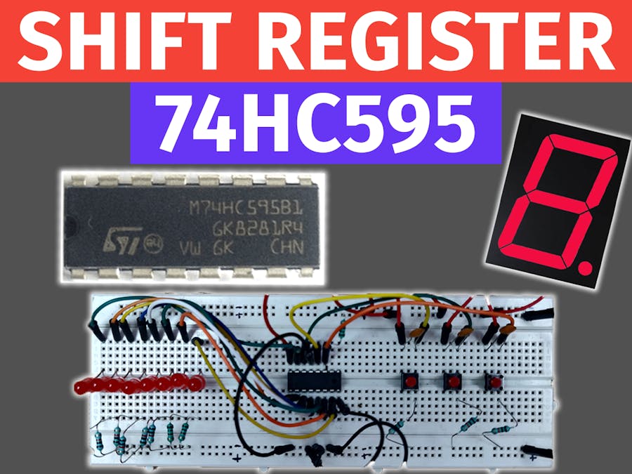
About 74HC595 Shift RegisterA 74HC595 Shift Register is a 16 Pin SIPO IC. SIPO stands for Serial In and Parallel Out which means that it takes input serially one bit at a time and provides output parallelly or simultaneously on all the output pins. We know that Shift registers are generally used for storage purposes and that property of the registers is used here. The data slides in through the serial input pin and goes on to the first output pin and remains there until another Input comes inside the IC as soon as another input is received, the previously stored input shifts to the next output and the newly entered data comes on to the first pin.
This process continues until the storage of the IC is not full i.e until receiving 8 inputs. But when the IC storage becomes full as soon as it receives the 9th input the first input goes out through the QH' pin if there is another shift register daisy-chained to the current register through the QH' pin then the data shifts on to that register otherwise it gets lost and the incoming data keeps coming in by sliding the previously stored data. This process is known as Overflowing. This IC uses only 3 GPIO pins to connect to the microcontroller and hence by consuming only 3 GPIO pins of the microcontroller we can control infinite devices by daisy-chaining a number of these ICs to each other.
A real-world example that uses shift register is the ‘Original Nintendo Controller’. The main controller of the Nintendo Entertainment System needed to get all button presses serially, and it used a shift register to accomplish that task.
Pin Diagram of 74HC595Though this IC is available in a number of varieties and models we will be discussing here the Pinout of Texas Instruments SN74HC595N IC. For more detailed information on this IC, you can refer to its datasheet from here.
The Shift Register IC has the following pins:-
1) GND - This pin is connected to the Ground pin of the microcontroller or the power supply.
2) Vcc - This pin is connected to the Vcc of the microcontroller or Power supply as it is a 5V logic level IC. 5V power supply is preferable for it.
3) SER - It is the Serial Input Pin data is entered serially through this Pin i.e. one bit at a time is entered.
4) SRCLK - It is the Shift Register Clock Pin. This pin acts as the clock for the Shift Register as the Clock signal is applied through this pin. As the IC is a positive edge triggered so to shift bits into the Shift register, this clock needs to be HIGH.
5) RCLK - It is the Register Clock pin. It is a very important Pin because in order to observe outputs on the devices connected to these ICs we need to store the inputs into the latch and for this purpose, the RCLK pin needs to be HIGH.
6) SRCLR- It is the Shift Register clear Pin. It is used whenever we need to clear the storage of the Shift register. It sets the elements stored in the Register to 0 at once. It is a negative logic Pin hence whenever we need to clear the register we need to apply a LOW signal at this pin otherwise it should be kept at HIGH.
7) OE- It is the Output Enable Pin. It is a negative logic pin and whenever this pin is set to HIGH the register is set into a high Impedance state and Outputs are not transmitted. To get the Outputs we need to set this pin to low.
8) Q1-Q7 - These are the Output Pins and need to be connected to some sort of Output like LEDs and Seven Segment Display etc.
9) QH' - This Pin is there so that we may daisy-chain these ICs if we connect this QH’ to the SER pin of another IC, and give both ICs the same clock signal, they will behave like a single IC with 16 outputs. Of course, this technique is not limited to two ICs – you can daisy-chain as many as you like if you have enough power for all of them.
Connecting Display With Arduino Through 74HC595So Now we have sufficient knowledge about the Shift Register IC hence we will head over to the Implementation part. In this step, we will do the connections in order to control SSD with Arduino through 74HC595 IC.
Materials Required: Arduino UNO, Seven Segment Display, 74HC595 Shift Register IC, Jumper cables.
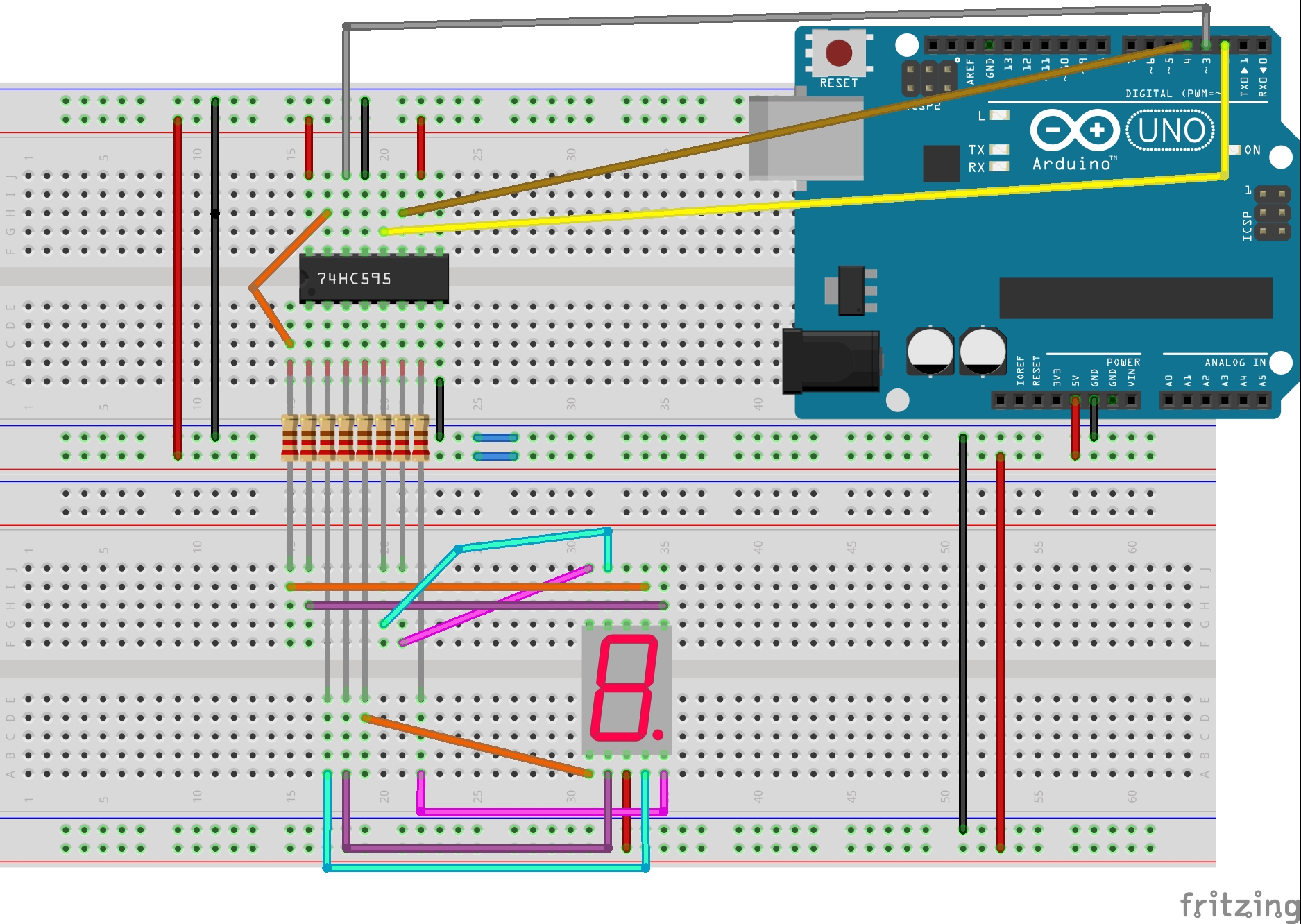
1) Connect the IC to SSD in the following manner:-
- IC Pin No. 1(Q1) to display pin for Segment B through a resistor.
- IC Pin No. 2(Q2) to display pin for Segment C through a resistor.
- IC Pin No. 3(Q3) to display pin for Segment D through a resistor.
- IC Pin No. 4(Q4) to display pin for Segment E through a resistor.
- IC Pin No. 5(Q5) to display pin for Segment F through a resistor.
- IC Pin No. 6(Q6) to display pin for Segment G through a resistor.
- IC Pin No. 7(Q7) to display pin for Segment Dp through a resistor.
- Common pin on the Display to either the power or ground rail. If you have a Common Anode Display, connect common to the power rail, otherwise for a Common Cathode Display connect to the ground rail
2) Connect Pin No. 10(Register Clear Pin) of the IC to the power rail. It will prevent the Register from clearing as it is an active low pin.
3)Connect Pin No. 13(Output Enable Pin) of the IC to the ground rail. It is an active-high pin hence when kept at low it will enable the IC to give outputs.
4) Connect Arduino Pin 2 to Pin12(Latch Pin) of the IC.
5) Connect Arduino Pin 3 to Pin14(Data Pin) of the IC.
6) Connect Arduino Pin 4 to Pin11(Clock Pin) of the IC.
7) Connect Vcc and GND of the IC to that of the Arduino.
After doing all these Connections you will end up with a circuit similar to that in the image above and after all these steps you need to head over to the Coding part.
Coding Arduino to Control Seven Segment DisplayIn this step, we will code the Arduino UNO to display different digits on the Seven Segment Display. The steps for it are as follows:-
1) Connect Arduino Uno to your PC.
2) Head over to the Github repository of this project from here.
3) In the repository open the "7segment_arduino.ino" file this will open the code for this project.
4) Copy this code and paste it into your Arduino IDE and upload it to the board.
As the code gets uploaded you will be able to see numbers from 0 to 9 appear on the Display at a delay of 1 sec.
You Can Make Your Own Like ThisSo by following all these steps you can make this project on your own which will look like the one shown in the image above. You can also try the same project without the Shift Register IC and you will get to know how this IC is helpful in providing outputs to multiple objects at once that too using a lesser number of GPIO pins. You can also try daisy-chaining a number of these ICs and control a large number of sensors or devices etc.
Hope you liked this tutorial.


_baVEVgguW1.jpg?auto=compress%2Cformat&w=48&h=48&fit=fill&bg=ffffff)


_3u05Tpwasz.png?auto=compress%2Cformat&w=40&h=40&fit=fillmax&bg=fff&dpr=2)

Comments
Please log in or sign up to comment.