In this article discuss about the interfacing of a 16x2 Liquid Crystal Display with Arduino Uno. And then read the analog value using the inbuilt ADC of Arduino Uno. Here I am going to connect the LCD in parallel way. We can also interface this LCD with only just 4 wires. (I2C communication is used there). Stay tuned for that article. This article help you to interface LCD with Arduino and make your project to fight against Covid -19
This article is mainly for beginners. The code explained line by line.
Key points.
- Specifiaction of is 16x2 LCD
- Hardware connections
- Liquid Crystal library functions( lcd.print(), lcd.Setcursor(), lcd.clear() )
- Read the analog value
- Finally print that analog value to display.
Why it is called 16x2 ? Because you can write 16 characters or numbers in column wise and 2 in row wise. This display have total of 16 pins. Here I only use 12 pins. Here we use the pins except D0, D1, D2, D3. Because here I interface the LCD in 4 bit mode.
The use of pins listed below
GND(VSS)
Connect the ground pin of the power supply to this pin.
VCC
Connect this pin to 5v
Contrast (VEE)
This pin is used to adjust the contrast of Display. Connect a potentiometer (POT) to this pin. Rotate the knob of the POT to adjust the contrast.
RS
RS pin means Register select pin. Selects command register when the pin is LOW. And selects data register when this pin is HIGH.
RW
It represent the Read Write pin. When this pin is LOW, the MCU write to register. And when the pin is HIGH, MCU read from the register. Here we want to write. It connect it permanently to GND.
EN (E)
EN pin means the Enable pin. Send data to data pins when a HIGH to LOW pulse is given.
D0-D7 (DB0-DB7)
These are 8 data pins. Here I interface this LCD with Arduino is in 4 bit mode. So we need only D4 to D7.
Backlight(+)
This is the anode pin of the backlight of the display
Backlight(-)
This is the cathode pin of the backlight of the display
Lets start!!!!!!!
First I am going to create a sketch for Arduino
Step - 1
Open Arduino IDE. Here we use "Liquid Crystal" library. This is an inbuilt library, so no need to install that library separately. First I am going to call this library.
#include <LiquidCrystal.h>Step -2
Next initialize the library with the number of the interface pins. With the function "LiquidCrystal lcd()". The function has six attributes. These are the interface pins in the order of "RS, E, D4, D5, D6, D7". Here we use pins 12, 11, 5, 4, 3, 2. corresponding to above.
LiquidCrystal lcd(12, 11, 5, 4, 3, 2);Step - 3
Now can call this display by "lcd". Next program the setup part. We need to set the number of columns and number of rows. Here I am using the LCD with 16 column and 2 rows. Set the number of columns and rows by the function "lcd.begin(16, 2)". If you have a display with 16 columns and 4 rows this become "lcd.begin(16, 4)". And set the A0 pin as input.
lcd.begin(16,2);
pinMode(A0,INPUT);
Step - 4
The setup part is over. Next loop part
First I am going to clear the display. For that I use the function "lcd.clear()". This function will clean the entire display.
lcd.clear();Step - 5
We need a starting point to start printing. So set the cursor to that particular point by the function "lcd.setCursor()". This function have only two attribute. It is that starting points.(The number of column and number of row). Here I am staring from first column first row. The first column is represented as 0, second is 1, and so on and the first raw is represented as 0, second is 1. So we need to start from the position (0, 0). You can easily understand if you know about matrix. The piece of code become,
lcd.setCursor(0,0);Step - 6
Next is the core part of this article. The instruction to print. I am going to print "Hello Hackster" by the instruction "lcd.print()". Alternatively you can print any thing. Please don, t forgot the double quote marks.
lcd.print("Hello Hackster");Step -6
In the above printing statement we use total of 14 characters. So the current position of cursor is at (14, 0). Next I am going to print on the next line, ie the position (0, 1). Set the cursor to that point by the function "lcd.setCursor()".
lcd.setCursor(0,1);Step - 7
Now the cursor is at the position of second row and first column(0, 1). Then print another text "Value" by the function lcd.print().
lcd.print("Value : ");Step - 8
Here we use 8 characters in second line. So the current position of cursor is (8, 1). Next we need to read the analog value from the pin A0. For more about analog value conversion please see my previous article here. And print it to the display. I use the function "analogRead()" function to read the analog value and use the "lcd.print()" function to print the value to the display. And there is no need of double qunotes.
lcd.print(analogRead(A0));Step - 9
Next I add some delay. Otherwise the text will blinks continusoly. That because of the first instruction "lcd.clear()". Every time when see this command the Arduino will clear the display, This results the blinking of display. But use of delay will decrease this blinking.
delay(500);The programming part is completed. The complete program is given in the code section of this article.
Step - 10
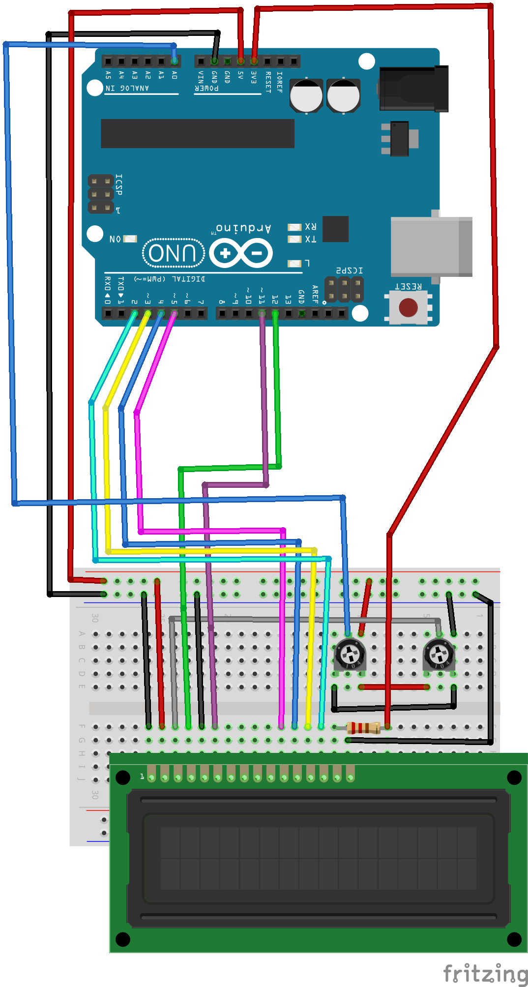
Connection
* LCD RS pin to digital pin 12
* LCD Enable pin to digital pin 11
* LCD D4 pin to digital pin 5
* LCD D5 pin to digital pin 4
* LCD D6 pin to digital pin 3
* LCD D7 pin to digital pin 2
* LCD R/W pin to ground
* LCD VSS pin to ground
* LCD VCC pin to 5V
* 10K POT:
* ends to +5V and ground
* wiper to LCD VO pin (pin 3)
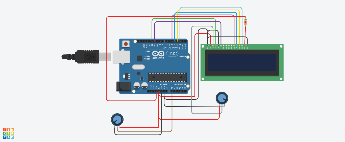
Connect the LCD to the Arduino Uno. You can use a breadboard or just use the jumber wires. For permanent connection use a LCD shield for Arduino Uno. The connection diagram is given in the Schematics part. Please careful about the backlight LED connection. Over voltage will kill that LED.
Please don't copy-paste my code. Try to understand the code line by line and create your own sketch.
You can see the tinkercad simulation here.
You can join our telegram group here or search INNOVATION.
Follow me on,
Instagram : five_volt_player
Contact : akshayjoseph666@gmail.com
Share your experience and suggestions on the comment box.
Previous articles :
Touchless Doorbell, Interfacing Bluetooth Module (HC-05) with Arduino Uno, Automatic Water Tap, Automatic Hand Sanitizer, Interface Ultrasonic sensor with Arduino Uno, Control Servo motor with Arduino Uno and Pushbutton, Control Servo motor with Arduino Uno and POT, Servo Motor Interface with Arduino Uno, IR Controlled Home Appliances With Saving Previous State, Touchless Hand Wash Timer


_ztBMuBhMHo.jpg?auto=compress%2Cformat&w=48&h=48&fit=fill&bg=ffffff)


Comments
Please log in or sign up to comment.