


Hardware components | ||||||
| × | 1 | ||||
| × | 2 | ||||
 |
| × | 1 | |||
 |
| × | 2 | |||
 |
| × | 4 | |||
| × | 2 | ||||
| × | 2 | ||||
 |
| × | 4 | |||
 |
| × | 2 | |||
 |
| × | 1 | |||
| × | 2 | ||||
| × | 2 | ||||
| × | 1 | ||||
I am designing Arduino shield for 2WD smartcar like this
The purpose is to create shield that will allow easy connection of sensors and control of motors including feedback from motor speed sensors like this.
I am planning to use:
- Three HC-SR04 ultrasonic distance measuring sensors
- Photoresistor for light measurement. Something like this
- Possible two Sharp infrared distance measuring sensors.
- Two motor speed photoelectric sensors.
Shield includes ATmega328 controller for motors control. Because I want to control motors using speed feedback from motor speed sensors, I think it will be good to have dedicated controller for this task. The idea is that main Arduino board will only need to transmit desired speed for each motor via I2C. Then controller located on shield will control motors using feedback from speed sensors.
Any comments and suggestions will be appreciated.
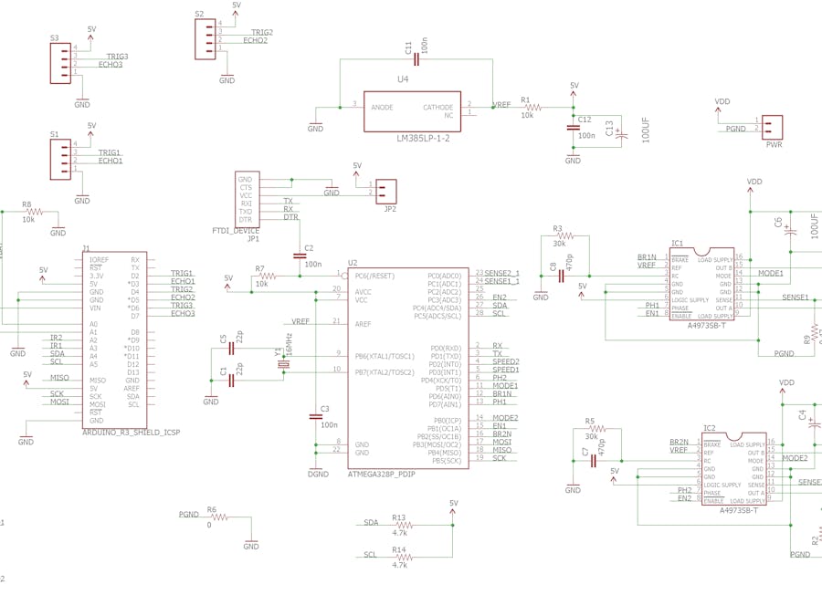
Schematic
Motor driver
ALLEGRO MICROSYSTEMS A4973SB-T chip was selected to drive motors.This chip has FET driving transistors, so low voltage drop expected, especially for low current motors, and minimum power will be wasted.
Chip allows constant motor current up to 1.5A and voltage 5V to 50V. In my case I need 120mA and 5-6V.
Driver total "ON" resistance is less then 1.5 ohm, so for 1A current voltage drop can be up to 1.5V. In my case as I need only 120mA, so voltage drop will be less then 180mV
According to SPEC DIP package can dissipate near 3W, so actually it seems possible to draw constantly up to 1A. This chip also has thermal protection and current limiting.
Current limiting
I added option to use current limiting option of driver.
R2,R9 0.47Ohm resistors used for current sensing. At least 0.5W resistors should be used to withstand motor stall and short circuit current.
TEXAS INSTRUMENTS LM385LP-1-2 Voltage Reference used to create 1.235V reference voltage. Current limit is 1.235/(2*0.47)=1.3A This is generally for short circuit protection as selected motor should have stall current less then 1A.
R3,C8 and R7,C7 recommended value used for current limiting.
Current sensing
R2,R9 current sensing resistors connected to A0,A1 analog inputs to enable motor current measurement and detection of motor stall. It may be useful to shutdown motors if stall detected and will prevent fast discharge of battery.
1.235V reference voltage also connected to AREF input of controller to improve accuracy of current measurement.
Connectors
JP1 - FDTI connector for programming ATmega328 controller
E1,E2 motor connectors
PWR - motors power generally can be 5V to 50V. For my motors 5V to 6V
S1,S2,S3 connectors for HC-SR04 sensors.
JP2 - jumper allows to power shield from FDTI connector (for initial debug)
IR1,IR2 - connectors for IR distance sensors
SS1,SS2 connectors for motor speed sensors
LIGHT - connector for light sensor
BAT - battery connector. This used to monitor battery voltage.
JP3 - jumper allows to connect voltage from PWR connector to Vin pin of Arduino
Pins used
D2-D7 pins used for HC-SR04 sensors
A4,A5 I2C communication
A3,A2 optional IR sensors
A1 optional light sensor
A0 optional battery voltage control
PCB


_3u05Tpwasz.png?auto=compress%2Cformat&w=40&h=40&fit=fillmax&bg=fff&dpr=2)
Comments
Please log in or sign up to comment.