

Hardware components | ||||||
 |
| × | 1 | |||
 |
| × | 1 | |||
Software apps and online services | ||||||
 |
| |||||
 |
| |||||
As IoT progresses, we see more and more developers taking advantage of ready-made boards that include everything from processing units to wireless connectivity modules.
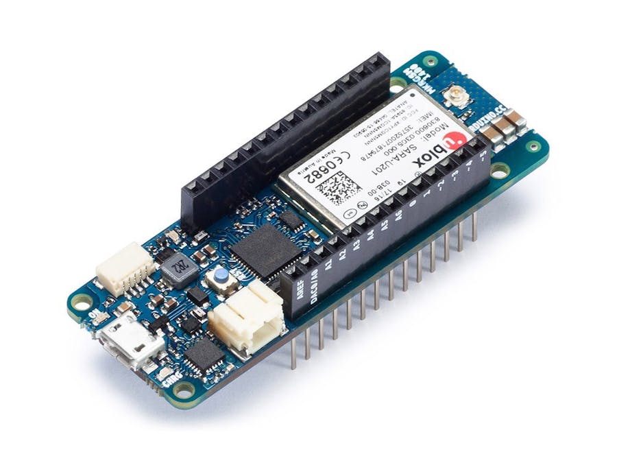
One such board is Arduino’s recently released MKR GSM 1400, based on the popular Arduino MKR family. The board includes a Cortex-M0+ 32-bit microcontroller, USB Serial port for development and debugging, and most importantly a pre-integrated cellular modem compatible with global 2G and 3G GSM networks. It also features low-power functionality, allowing us to build solutions that can run solely on battery.
Let's look at how to use the MKR GSM 1400 to collect and visualize data from a battery operated IoT sensor over a cellular connection.
To build this project, you will need the following items:
- A computer running Linux, MacOS or Windows
- Arduino MKR GSM 1400 board (Arduino Store)
- 3G GSM Antenna with U.FL connector (Amazon)
- Micro-USB cable for programming and troubleshooting (Amazon)
- DHT11 Sensor (Amazon)
- Breadboard and wires (Amazon)
- Soracom Air SIM card (Soracom)
We’ll start by activating the SIM card:
- Once you have the SORACOM SIM in hand, go to the Soracom User Console: https://console.soracom.io
- Go to SIM Management and select REGISTER
Now we can prepare the data storage and analytics environment. First, we’ll create a Group and attach the SIM to it. Groups allow you to activate and configure specific services for specific SIMs. In this case, we’ll use SORACOM Harvest, which allows for quick data storage and visualization from connected devices.
- Create a new group, choose a name of your liking
- At the bottom of the screen, open the “SORACOM Harvest” box and switch Harvest to ON. Then click SAVE.
- Now that your group is active, return to the SIM Management tab and assign the group to your new SIM by selecting it and clicking on Action > Change Group.
Now that the Soracom platform side has been configured, let’s assemble the sensor device.
- Insert your SIM card on the back of your MKR GSM 1400
- Add it on the Breadboard and connect the antenna
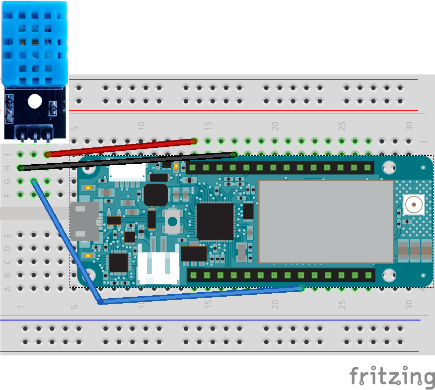
- Add in the DHT11 sensor and wire the VCC (red), DATA (blue)and GROUND (black) wires per the below schema:
Note: Be careful with VCC and GROUND as they are often swapped between different DHT11 manufacturers.
This project wiring is as follows (you can see the pin names/numbers on the side of your MKR board):
RED: MKR GSM 1400 VCC to DHT11 VCC
BLACK: MKR GSM 1400 GROUND to DHT11 GROUND
BLUE: MKR GSM 1400 pin 0 to DHT11 DATA
Once your Arduino and Sensor have been assembled, connect your the Micro-USB cable to it and to your computer. The end product should look like the one below:
Now that our SIM card & Soracom Platform have been configured and Arduino MKR GSM assembled, we’ll write the device software and upload it to the Arduino Board.
To get started, download the Arduino IDE at https://www.arduino.cc/en/Main/Software?
Once the Arduino IDE has been installed on your computer, you’ll need to download additional board support. Start the Arduino IDE and install it from the top menu Tools > Board > Boards Manager:
- Arduino SAMD Boards: Search for “MKR” to find and install it
For this project we also need additional libraries support which you can install from the top menu Sketch > Include Library > Manage Libraries
- MKRGSM Library: Search for “MKRGSM” to find and install it
- DHT Sensor Library: Search for “DHT” to find and install it
- Adafruit Unified Sensor Library: Search for “Adafruit Unified Sensor” to find and install it
Now the fun starts. With all the Libraries installed, we’re ready to code the Arduino board. You can find sample code in our Github project athttps://github.com/alexissusset/soracom-mkrgsm1400
- Click on “Clone or Download” button to get a copy of and double click on MKRGSM_1400_DHT_HARVEST.ino to open it in Arduino IDE.
- Click on the arrow on the top left to upload it to your Arduino
- Then open the console using the top right button to see what your device is doing
The console will look as shown below and will show you if the device is working as expected:
As you can see in the above console, our DHT11 sensor is working and we were able to send data to Soracom Harvest.
5. Visualise the dataNow to visualise your data, go back to Soracom Console, select your SIM card in the list and click on top menu Actions > Harvest Data.
You will be presented with a graph showing your sensor data along with the full list of collected data points.
That’s it! You now have a cellular-connected MKR GSM 1400 Sensor that will work anywhere you have coverage. If you’d like to run the device independently from a computer, you can plug it directly to a USB power source such as a phone charger or USB Battery.
As well as automatically visualising you data on single or multiple devices, Harvest will also let you query the data via our APIs and CLI so you can integrate it into your applications and processes.
Alexis Susset
 Rickster


Comments
Please log in or sign up to comment.