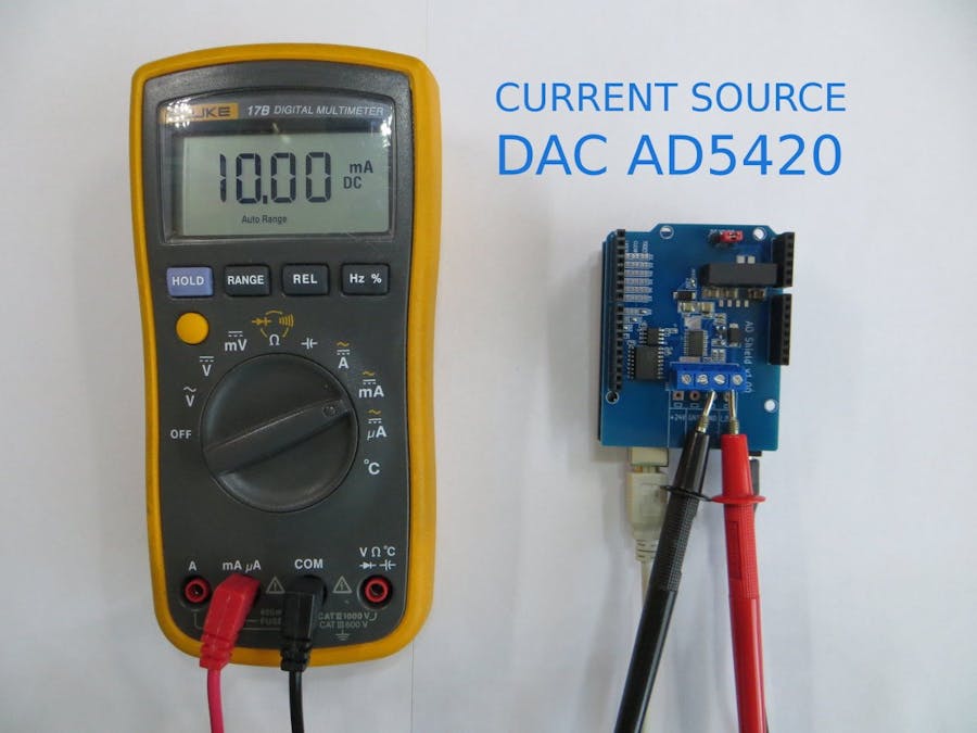
Hello.In this article, I would like to share my experience with the AD5420 current digital-to-analog converter, which has the following characteristics:
- 16-bit resolution and monotonicity
- Current output ranges: 4 mA to 20 mA, 0 mA to 20 mA, or 0 mA to 24 mA
- ±0.01% FSR typical total unadjusted error (TUE)
- ±3 ppm/°C typical output drift
- Flexible serial digital interface
- On-chip output fault detection
- On-chip reference (10 ppm/°C maximum)
- Feedback/monitoring of output current
- Asynchronous clear function
Power supply (AVDD) range
- 10.8 V to 40 V; AD5410AREZ/AD5420AREZ
- 10.8 V to 60 V; AD5410ACPZ/AD5420ACPZ
- Output loop compliance to AVDD − 2.5 V
- Temperature range: −40°C to +85°C
For work, I took the following components:- Arduino UNO,- AD5420 shield for Arduino (with galvanic isolation),- Multimeter (for measuring the output current).
At the first step, it is necessary to install jumpers on the shield that are responsible for choosing the voltage level of logical signals:
as well as for selecting FAULT, CLEAR and LATCH signals:
In the second step, I connected the AD5420 shield to the Arduino UNO, connected the 9-12V power, the USB cable for programming, a Multimeter for measuring 24V voltage (from an internal source):
Having connected the power, I immediately saw a voltage of 24V (which actually was a little higher):
After controlling the voltage, I switched the Multimeter to measure the current at the output of the shield:
Next, I programmed the sketch in Arduino UNO. The sketch and the necessary library are attached below:
/*
THIS CODE IS STILL IN PROGRESS!
Open up the serial console on the Arduino at 115200 baud to interact with FONA
Note that if you need to set a GPRS APN, username, and password scroll down to
the commented section below at the end of the setup() function.
*/
#include <ad5420.h>
/*
Use the 6 pin SPI connector on arduino DUE board (NOT the ICSP!)
The pin 1 has a white dot behind it.
MOSI:
MISO:
SCLK:
CS: on SPI extended mode can use only PIN 4,10,52 !!!
*/
#define AD5420_FAULT  8
#define AD5420_CLEAR  9
#define AD5420_LATCH 10
DAC_AD5420  dac_ad5420 = DAC_AD5420(AD5420_LATCH, AD5420_CLEAR, AD5420_FAULT);
uint16_t  current = 0;
void setup()
{
Serial.begin(115200);
Serial.println("AD5420_test start!");
Serial.print("_latch = ");
Serial.println(dac_ad5420._latch);
Serial.print("_clear = ");
Serial.println(dac_ad5420._clear);
Serial.print("_fault = ");
Serial.println(dac_ad5420._fault);
dac_ad5420.begin();
delay(100);
dac_ad5420.ad5420_reset();
delay(100);
dac_ad5420.ad5420_write_ctrl(AD5420_OUTEN | AD5420_REXT | AD5420_0_20_RANGE);
//    dac_ad5420.ad5420_write_data(0x2000);
dac_ad5420.ad5420_write_data(current);
}
void loop()
{
Serial.print("Get_Status: ");
Serial.println(dac_ad5420.ad5420_get_status(), HEX);
Serial.print("Status_Reg: ");
Serial.println(dac_ad5420.ad5420_read_reg(AD5420_STATUS_REG),  HEX);
Serial.print("Data_Reg: ");
Serial.println(dac_ad5420.ad5420_read_reg(AD5420_DATA_REG),    HEX);
Serial.print("Control_Reg: ");
Serial.println(dac_ad5420.ad5420_read_reg(AD5420_CONTROL_REG), HEX);
if(Serial.available() > 0) {
char  ch = Serial.read();    // Clean the input buffer
if (ch == '0') dac_ad5420.ad5420_write_data(0x0000);
else
if (ch == '1') dac_ad5420.ad5420_write_data(0x1000);
else
if (ch == '2') dac_ad5420.ad5420_write_data(0x2000);
else
if (ch == '3') dac_ad5420.ad5420_write_data(0x3000);
else
if (ch == '4') dac_ad5420.ad5420_write_data(0x4000);
else
if (ch == '5') dac_ad5420.ad5420_write_data(0x5000);
else
if (ch == '6') dac_ad5420.ad5420_write_data(0x6000);
else
if (ch == '7') dac_ad5420.ad5420_write_data(0x7000);
else
if (ch == '8') dac_ad5420.ad5420_write_data(0x8000);
else
if (ch == '9') dac_ad5420.ad5420_write_data(0x9000);
else
if (ch == 'A') dac_ad5420.ad5420_write_data(0xA000);
else
if (ch == 'B') dac_ad5420.ad5420_write_data(0xB000);
else
if (ch == 'C') dac_ad5420.ad5420_write_data(0xC000);
else
if (ch == 'D') dac_ad5420.ad5420_write_data(0xD000);
else
if (ch == 'E') dac_ad5420.ad5420_write_data(0xE000);
else
if (ch == 'F') dac_ad5420.ad5420_write_data(0xF000);
else
if (ch == 'G') dac_ad5420.ad5420_write_data(0xFFFF);
}
delay(1000);
}
After programming, I opened the Serial Monitor, into which debugging information is issued, and through which you can set the current value from 0 to 20 mA in increments of 1.25 mA. I decided not to complicate the sketch, but to make it as simple as possible, so I set the current in numbers and letters 0-9 and A, B, C, D, E, F, G. A total of 17 values, 16 intervals, therefore, the step is 20mA / 16 = 1.25mA.
At the last step I checked the detection of an open circuit, for this I broke the measuring circuit and found that the status register changed the value from 0x00 to 0x04:
Results: The current source DAC is stable, has high accuracy. The presence of galvanic isolation allows its use in hazardous industrial areas.


_ztBMuBhMHo.jpg?auto=compress%2Cformat&w=48&h=48&fit=fill&bg=ffffff)


Comments
Please log in or sign up to comment.