


What Do I Build Next? Beware this is the most expensive robot I've ever purchased and built at over $1000.00 USD even with a 10% discount ordered directly from Yahboom.
Here is the finished product video, the Transbot-Pi using LIDAR for obstacle avoidance, you can view and decide if its worth it....but ultimately there is a lot of user training involved JuypiterLab, ROS, Rviz, Rtab and a host of other AI software.
"
Let me back up in history... just about 6 weeks.
It was the Christmas season 2021 and I wanted to build a more advanced Raspberry Pi based autonomous robot, but I didn't want to use just ordinary ultrasonic sensors. After a lot of software and hardware investigation and purchasing and testing and building a robot using OPENCV to perform image characterization, I stumbled upon an inexpensive LIDAR assembly.
I joke about inexpensive term because a few years ago I built whole robots for less than $100.00 USD and the "RPLIDAR by Slamtec" was being sold on Amazon for $99.00 " Amazon.com : rplidar" " Amazon.com : Slamtec RPLIDAR A1M8 2D 360 Degree 12 Meters Scanning Radius LIDAR Sensor Scanner for Obstacle Avoidance and Navigation of Robots : Electronics ".
This product was marketed as configurable using Windows, Linux, Arduino using a Windows PC, a Raspberry Pi, a Jetson Nano, and even an Arduino. Guess what? I have all these SBC's (single board computers) available to test and develop with.
I even got a $20.00 USD discount on the RPLidar when I purchased it (so it cost me $80.00 USD), but I forget why I got that discount. I placed my order and three days later it arrived.
While I waited for delivery I investigated documentation, software, and videos showing this 2D Lidar in action and its 360* mapping capability. I was excited but that was short-lived. This info was for older versions of software that was not available now... Ubuntu 16.04, ROS 1.0, Ubuntu 18.04, even my Windows 11 and 10 laptops baulked at testing or even "discovering" this device. My Raspberry Pi 3B+, my 4B's, my Jetson Nano, and even Arduino Uno and Mega could not discover or load the CH341 USB to serial driver / CP210x Universal USB driver that interconnected between the RPLidar and the SBC's.
The CH341 / CP210x USB device was never recognized but the RPLidar got power and rotated at its nominal speed but the activity LED never illuminated on this USB interconnect board. I initailly thought my USB board was defective and Amazon sent me a complete replacement assembly. Both units never were detected by any of my devices although the software installs were successful. After two weeks of emails to associated vendors and tech support, I RETURNED both units and chalked LIDAR failure to education and experience.
I also was tempted to purchase a similar robot by " YouYeeToo for $678.00 USD "
Amazon.com: youyeetoo Ackerman Open Source AI Robotic Car kit Used to Learn Robot Operating System to Realize Vision or lidar Mapping, face Recognition and Smart Follow (Raspberry Pi Master Not Include Battery) : Industrial & Scientific " but after conferring directly with their tech support and marketing group about my concerns for the robustness of the product and lack of completeness in documentation at that time- we both decided that I should not buy their kit. I've never had a vendor say to me "Don't buy our product".
Back on December 10, 2021, I found that Yahboom was marketing a Jetson Nano version robot with all the features below; (but after email exchanges with their tech support, I decided to hold off for the Raspberry Pi version that was still under development.)
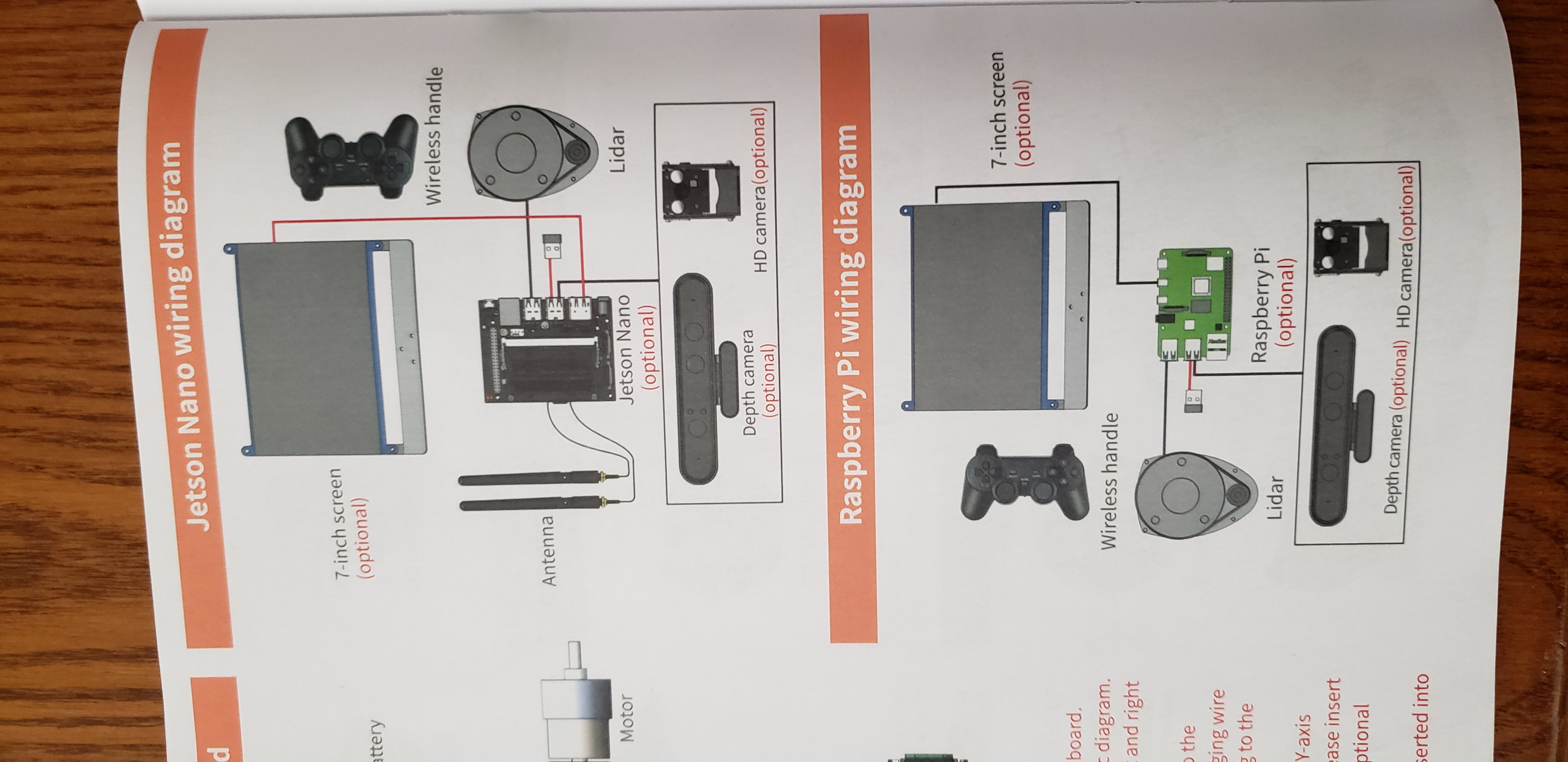
A complete Robot with the RPLidar, HD and Depth Cameras, a robotic arm, a 7 inch HDMI screen, a tank chassis, and controlled by a Jetson Nano or a Raspberry Pi 4B with 4gb/8gb ram and the software was based upon Ubuntu 18.04 and ROS and OPENCV; but with a starting price tag of $749.00 USD up to $1349.00 USD (5 different versions available). produced by Yahboom. Yikes!!!!
" Yahboom ROS Transbot Robot with Lidar Depth camera support MoveIt 3D m " I opted to supply my own Raspberry Pi 4B with (4gb or 8gb memory) at a substantial savings of $300.00 USD. I purchased it last week when the Raspberry Pi version officially went on sale on January 4, 2022 with a savings 10% of the website price and it was shipped via DHL and was delivered on 1/13/2022 a day early than expected.
Below is Yahboom's product information copied from Amazon's website:
*******************************************
- ★★★Note:Yahboom recommends Raspberry Pi 4B 8GB, although Raspberry Pi 4B 4GB can also be used, but it will freeze. Raspberry Pi & Jetson Nano are NOT included in any version
- 【Based on ROS Programmable Project Professional Kit】using rviz, TF, QT, navigation and other tools, combined with lidar and depth camera, transbot realizes 2D3D mapping navigation, path planning and other functions, learns ROS from scratch, and journey of ROS programming with Transbot.(★Note: check the version you ordered carefully)The Raspberry Pi version of Transbot can achieve multi-vehicle control.
- 【RTAB-VSLAM 3D Visual Mapping Navigation】Astra Pro 3D Camera provided by version III supports 3D mapping navigation technology (rtab) containing pure vision and visual radar fusion. Transbot robot can navigate, avoid obstacles and global relocation in the 3D map, and quickly obtain image data such as camera depth map, color map, and skeleton through the corresponding API., based on the image related KCF filter algorithm, any follow target in the image can be selected. Beginning of the 3D world
- 【AI Function Combination】The robot integrates a wealth of AI functions, such as intelligent patrol, radar guard and tracking, fixed-point navigation, automatic driving, color recognition and tracking, AR tag recognition and reality enhancement, visual image beautification, face detection, lidar mapping navigation and obstacle avoidance, you will get the open source code provided by Yahboom to realize more possibilities.
- 【Cross-platform Interconnection Control】Robot can be programmed or controlled in 4 ways, ① Mobile remote control APP integrated with a variety of AI functions, ② handle control that can experience the FPV real-time visual effects, ③ JupyterLab online programming and ④ professional robot operating system control, a variety of control methods to meet different occasions, in-depth experience of the fun of controlling robots (★Note: Yahboom App supports iOS&Android, ROS robot APP only for Android)
- 【Professional Hardware】Transbot has highly equipped aluminum alloy frame, anti jam bearing, SLAM lidar, coding gear motor, metal servo, Yaboom professional robot expansion board, somatosensory depth camera (Optional), which makes the robot have strong ability to cross obstacles.
- 【Courses】Yahboom provides 64 video tutorials and detailed documentation. As long as you love ROS, it is robot that can 't be missed and professional gift that makers and programmers dream of. Yahboom provides professional technical help, leave your questions on the page or contact us.
- *****************************************************
I was sold with the features... please emotions, don't make me cry... so now for my build,
I quickly downloaded and viewed available documentation from the " http://www.yahboom.net/study/Transbot-Pi " website.
{Be advised this is not a "secure website", I received security notices about being careful of personal information/hacking.}
"but most of all the "Transbot-Pi RPi4B image that was for a 32gb SD card. I am now ordering 64 gb SD Cards because these advanced image processing/AI products need space to store pictures used for "training algorithm's".
The kit came with a 32gb SD card with an image but I was unsure of its status so I created my own 64gb image to begin customization and localization and hooked up a HDMI monitor and keyboard and mouse to my RPi4B with 8gb ram and waited. It quickly booted a custom version of Ubuntu, I believe 18.04, and in a terminal window the Transbot/ROS software began running... naturally with errors since no peripherals were connected but I was able to change language and timezone to English only and "America/New_York" after looking up Ubuntu commands. via (timedatectl set-timezone America/New_York ) and (sudo date -s 22-01-14 17:43:00).
Not being well-versed with Ubuntu 18.04 commands, I didn't want to mess with the Transbot AP that was running " on the IP range of 192.168.x.x range", but I wanted to ensure that my local nic was connecting "10.0.x.x range" and they were.
Just an added note: Yahboom has pre-assembled most of the Transbot vehicle; saving many hours for even the experienced builder. The end result, was to install just the optional peripherals purchased. It took about 2.5 hours to install my options and that included viewing a couple of assembly videos.
I was done for preliminary efforts (and had battery charging) and needed time-off for "Playoff FOOTBALL" on Saturday, January 15th, but I had hoped to begin assembly before the 1st game, but spent most of day reviewing assembly videos that incorporated a Youtube video playlist that was not in correct order.
My Assembly Steps:
1. Unbox
2. Layout and identify contents
3. Install HD Camera or Depth Camera (optional choice- I purchased both)
I will be installing the Orbbec Astra Depth Camera. I believe Yahboom's videos have the HD Camera and Depth Camera mislabeled but maybe that's my misunderstanding.
A. First gather the Depth Camera Rotary mount, with "Y- Yoke" and from Bag 4, a M6 Hex screw, four M2 Screws, two M3 screws and split washers, Camera mounting bracket, Bag 2- a wrench.
B. Install Rotary mount on Transbot rotary bearing assembly on chassis using the M2 screws and split washers
C. Attach the Camera mounting bracket to the bottom of the Depth Camera with the M6 Hex screw, and have the bracket face with two screw holes facing forward
D. Mount the Depth Camera to the rotating "Y-Yoke mount" using two M3 screws and split washers from Bag 4.
E. Install a flex/flat cable tie to rear Camera mount. WHY? I could not figure from video...
F. The Depth camera USB cable will be installed at a later step
" Orbbec Astra Depth Camera... Yahboom video
I will later be removing the 3D Depth camera and installing the HD Camera to test its video performance by following these steps.
A. Gather the following hardware: the HD Camera, the HD Camera mounting caddie for rotary mount, Bag 5- four M2 Screws, eight M3 screws and split washers for each.
B. Attach the HD Camera Rotary mount to the Rotary bearing collar on the Transbot chassis using the four M2 screws and split washers
C. Insert the HD Camera into the HD Camera Caddie and secure together using the four M3 screws and split washers
D. The HD Camera cables will be attached at a later step
" or " HD Camera... Yahboom video
"
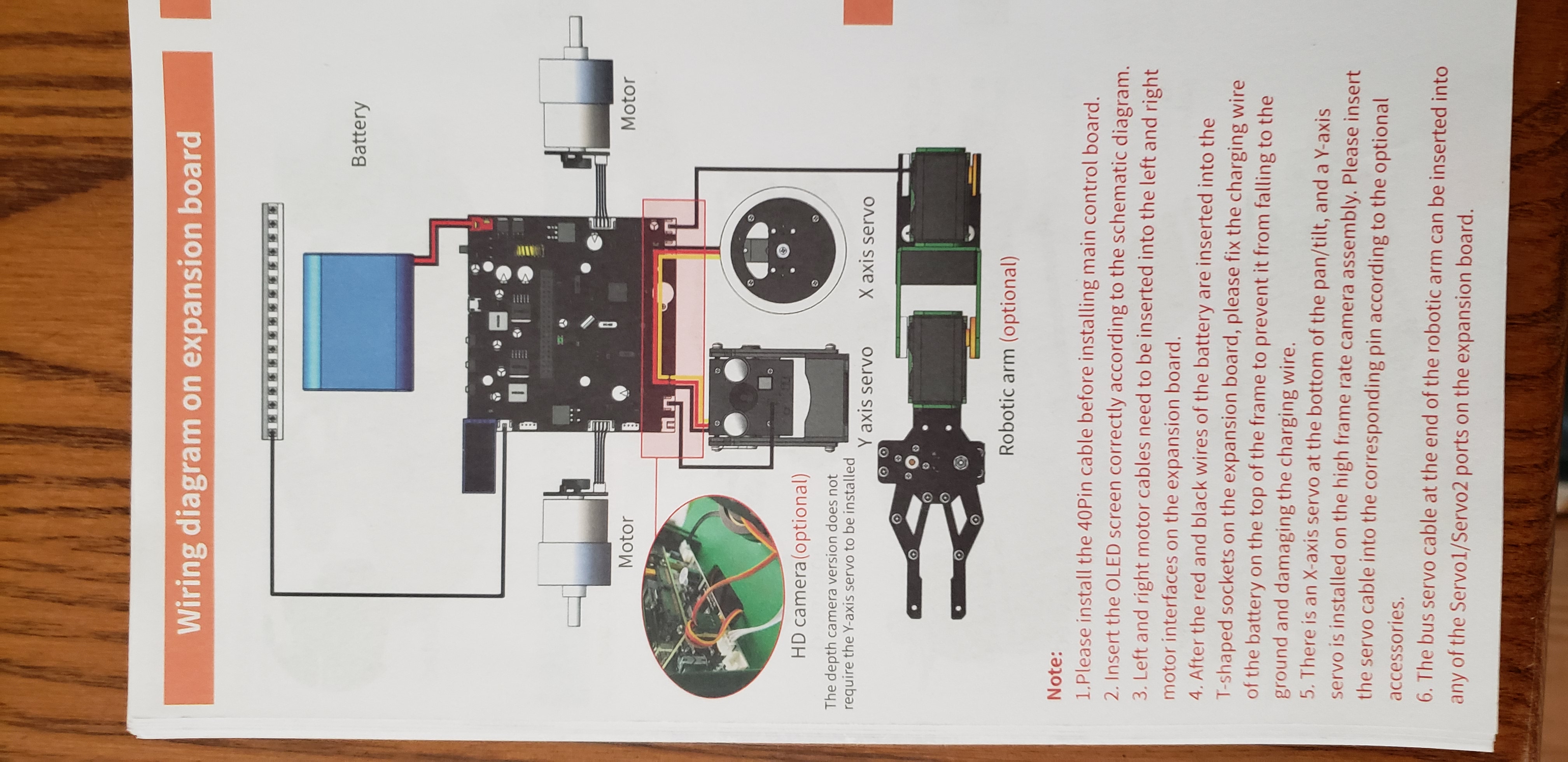
4. Install Robot Interface IO Board
A. Gather the following hardware: the Robot Interface IO board, Bag 1- four M2.5*11+6 mm copper columns/standoffs, Bag2- four M2.5*19+6 mm copper columns/standoffs, two M2.5 lock-nuts, and the PI bag- a wrench, with four M2.5*14+6 copper columns/standoffs
B. Attach two M2.5*19+6 copper column/standoffs to the center two mounting holes on the Robot Interface IO board and secure with two M2.5 lock-nuts and tighten with the PI wrench. Pay attention, use the longer standoffs to provide spacing between Raspberry Pi and Robot Interface.
C. Install four M2.5*19+6 copper column/standoffs to the four tapped holes around the large opening in the Transbot chassis.
D. Install the Robot Interface IO board onto the four M2.5*19+6 copper column/standoffs (IO boards with buttons to rear) using two of the M2.5*19+6 copper columns in the rear and two M2.5*5 mm screws in the front by Camera.
E. Connect the Depth Camera servo cable to the servo X port, and the Camera USB cable will be installed at a later step
F. Connect the Motor A and Motor B IO cables to the Robot Interface IO board in the labelled ports
G. Connect the rear LED 3 wire IO cable to the labelled LED port
Yahboom's video below is labelled Jetson NANO board installation video but it is for the Raspberry Pi 4B+
"
"
5. Install Raspberry Pi 4B with 32gb Yahboom Transbot image and Cooling fan module and LCD display; I used a 64gb SD card so future content and pictures can be stored and manipulated locally.
A. Gather the following hardware: it is best to use a Raspberry Pi 4B with 8gb ram I was informed by the vendor but at a minimum the 4gb version could be used. Next the 40 pin GPIO cable, the small LCD display, and from Bag1- four M2.5 screws, from the PI Bag-four M2.5*14+6 copper columns.
B. Install the 40 pin GPIO ribbon cable onto the Robot Interface IO board connector with Red wire orientated so cable folds over itself and is routed towards camera. Pay attention to 40 pin GPIO orientation in connector and routing
C. Attach the Raspberry Pi 4B onto the four M2.5*19+6 copper column standoffs that were installed onto the Robot interface IO board using four M2.5*14+6 copper column standoffs
D. Attach the Cooling fan module onto the Raspberry Pi's 40 pin GPIO connector and secure in place using Bag 1-four M2.5*5 mm screws
E. Attach 40 pin GPIO ribbon cable the 40 pin header on cooling fan (proper orientation)
F. Install LCD display onto port on Robot Interface IO board
6. Install LIDAR assembly
A. Gather the following items: the RPLIDAR A1M8 module, box, the RPLIDAR assembly, the USB interface module, its USB IO cable, the RPLIDAR interconnect cable "very fragile", From BAG 2- two M6*10 hex screws and washers and from BAG 6- four M2.5 screws and washers, four M2.4+4 copper column/standoffs and the LIDAR mounting plate. A M6 hex wrench and philips/cross screwdriver will also be required and are included.
B. Attach fragile RPLIDAR interconnect cable to ports on underside
C. Attach RPLIDAR to LIDAR mounting plate
D. Attach four M2.4+4 copper column/standoffs to underside of LIDAR mounting plate
E. Attach RPLIDAR USB Interconnect board to LIDAR mounting plate
F. Using two M6*10 hex screws and split/lock washers from BAG2 attach to square standoffs
"
"
7. Install LCD screen module and Battery
A. Gather the 4 line LCD screen module and attach to port on Robot interconnect board
B. Gather the Battery Pack cover, the Battery pack, from BAG 1- four M4.8 screws and split/lock washers and a philips/cross screwdriver
C. Flip the Transbot upside down exposing its underside
D. Insert the battery pack into the battery pack cover and route cables through slot in case. These should be routed facing the installed motors
E. Install the four M4.8 screws through the battery cover into the Transbot case in the holes in each corner of the cover
F. Ensure that the Robot Interface Board's power switch is in the OFF position
G. Carefully attach the battery's "T-plug" onto the jack on the Interface board
"
"
8. Install Robot Arm (optional)
A. Gather assembled Robot ARM/Manipulator assembly, BAG 7- three M3.6 screws and split washers, ARM Mount
B. Attach ARM Mount with the three M3.6 screws to front of Transbot chassis
C. Loosen and remove ARM assembly locking screw from manipulator assembly. It is the large screw with a loop.
D. Position the ARM assembly onto the mounting bracket (release the quick release knob)
E. Thread the looped large screw from step C. threw hole in underside of Transbot chassis into threaded hole in manipulator. Tighten to secure in place
F. Route and connect the 3-wire servo black cable to the servo port on the Robot Interface port (outside right white port)
G. Connect the 3-wire (Orange/RED/Black) servo wire to port servo-X port.
"
"
9. Install 7 inch Screen (optional)
"
"
Connect Wiring
10. Create/Install Transbot SD Image
A. First go to the " http://www.yahboom.net/study/Transbot-Pi" website and download the appropriate "tools" and Raspberry Pi SD image. The "tools" directory includes an SD card formatter and the imaging tool to create the SD image. I already have the SDFormatter utility by Trendy Co. and the Balena.IO imaging tool. You could also use the Raspberry Pi IMAGER utility as well as select "custom image" to use.
11. Charge battery
A. The included 12 VDC charger is to be used only with the Transbot Power switch in the OFF position. This is to prevent the batteries from exploding... due to over heating. I allowed the batteries to charge overnight. When charging, the indicator LED on the charger wall plug will illuminate RED, when complete it will change to Yellow/Green.
12. Follow online training schema and videos for WIFI Controller or Android/IOS cell phone APP. These can be found at GOOGLE store under YAHBOOM. There are two Android APPs. One is called YAHBOOM ROS ROBOT and the other YAHBOOM ROBOT.
The ROS Robot controls the Transbot Robot via the ROS application directly and requires more knowledge than I presently have and the YAHBOOM ROBOT APP is more feature driven and easier to use, learn, and play. Both APPS require some hands-on direct connect interaction first.
A start-up overview: (Be advised, I had an initial power up issue with all options connected to the Raspberry Pi's USB ports. My LIDAR assembly would not spin or power ON. I troubleshot by unplugging items from the Pi's USB ports. Apparently the ORBBEC ASTRA 3D camera uses too much current than the Raspberry Pi can deliver when the HDMI screen, LIDAR, the WIFI dongle, and the 3D camera are connected. I was able to hookup the HDMI screen "touch" port cable to an external 5V 2A battery pack and this allowed the HMDI screen to power ON as well as all other options. The HD Camera does not require as much current as the Depth camera and when the HD Camera was installed allowed all the other options to start and function as expected)
Another note: the optional Robot Arm/manipulator is in both camera views when installed and blocks FPV video of lower area when navigating using "Remote control" feature in wifi/cell phone application. The Arm has a quick disconnect hub assembly and can be removed if not required for for testing. I found the camera(s) position did not allow adequate visibility for FPV pick-n-place of objects when using the cell phone APP.
I would recommend initially connecting an external HDMI screen and keyboard to the Raspberry Pi and observe the boot sequence and software loading. This was so you can see the "BIG PROGRAM" load and operate. The "BIG PROGRAM" is the Chinese term for the MAIN Application that loads upon start up in a "TERMINAL WINDOW" on the Ubuntu 18.04 Desktop. This program starts all the required software and looks for the various modules that the user has connected.
The first thing the user needs to identify is the WIFI IP address for the TRANSBOT ROBOT. The TRANSBOT ROBOT will launch its own local AP "access point", typically at 192.168.1.11 in my case. Once the "BIG PROGRAM" is running, The WIFI IP address will be displayed on the LCD display that is connected to the Robot Interface. The end user requires this IP address to use in either remote cell phone app.
For access with a cell phone, you'll need to connect to this AP via your cellphone's wifi settings "YAHBOOM was the SID and the password is 12345678". Once the "BIG PROGRAM" is running and you know the WIFI IP address of the TRANSBOT the cellphone application will scan and automatically search, find and configure itself for use.
There is a manual method that is described in the online documentation that requires a QR Code symbol to be generated and held up in front of the TRANSBOT ROBOT after the ROBOT has been placed in a WIFI configuration Mode after pushing a button on the Robot Interface board. Once again, this is written up in the online documentation, but I didn't need to reconfigure my access.
Below are screenshots of the included manual, that is a reference for assembly options and basic functions of the YAHBOOM ROBOT application.
" http://www.yahboom.net/study/Transbot-Pi " training courses
"
" YAHBOOM's playlist Videos are spoken in the Chinese language with English subtitles.
On January 23rd, 2022 when returning to edit and add content to this project; I discovered that Yahboom has released their official Transbot content on Hackster.IO on December 15th, 2021. It can be found here: Yahboom Transbot ROS Educational Lidar Robot - Hackster.io " https://www.hackster.io/yahboom/yahboom-transbot-ros-educational-lidar-robot-141ac2 ". Although their version uses the Nvidia Jetson NANO 4GB B01.
Here are my videos:
In summation, without using a separate battery for the HDMI screen or by installing the HD Camera instead of the Depth Camera I must make choices due to power requirements. I had envisioned displaying 3D Mapping using ROS/RVIZ on the HDMI screen on the Transbot. All Yahboom training videos are unclear of that. It could be that this is displayed through the end-users screen using remote desktop access, but data collected has to come through the Transbot, RLIDAR, the Depth Camera and the ROS software for processing. The Mapping of the environment is incremental and layered so there is a lot a processing involved in the background that goes unseen using the YAHBOOM ROBOT app instead of the YAHBOOM ROS app. I am probably wrong about my assumptions about mapping requirements and time will tell.
Well, that was the basic operation of this Transbot Robot. I will expand later when I learn about using the ROS ROBOT application to perform 3D environment MAPPING using RVIZ and other more advance features of this LIDAR robot.
So far, I've learned that LIDAR is used for obstacle avoidance, other its output is not displayed by default. Mapping of the environment will involve a deeper and better understanding of the LIDAR software and ROS. The Yahboom videos are in Chinese language with English subtitles. My initial viewing of these 60 or so videos with audio ON and then OFF was confusing, but did point me into the need to use multiple laptops or PCs and create a training environment just for this Advanced AI. These videos also showed that this environment setup had additional requirements not stated. I counted at least eight different IP Addresses for computers and possibly three different Transbot IP's used during the creation of these videos. (I'm a geek and I began to notice different IP addresses being used in the videos and there was also a Virtual Machine as well).
Today is January 31st, it's been an interesting 6 weeks plus.


Comments
Please log in or sign up to comment.