We all know the fictitious but very popular secrete agent character Jems Bond. Mostly he is well known because of his futuristic gadgets. Before 15 to 20 years in one of Bond movie, the Jems Bond has used the car that gives various voice indications like “door is unlocked please lock the doors”, “please wear seat belt” etc. In that era, it was just an imagination of script writer or director. But today this thing has become reality.
Some of the auto mobile manufacturers like AUDI, BMW, and Mercedes have added such sophisticated features in their cars that give audio-visual notifications for different events. One of the most useful notifications is door lock-unlock alarm. If any of the four doors is not properly locked then before starting the car it gives alert message. When all doors are properly locked it gives confirmation that doors are properly locked. The message or notification is given on dashboard display
So how this is possible? This is possible due to sensor. The sensors are attached to door locks of car. They generate electrical signal when door is locked or unlocked. These signals are fed to central computer (controller) to detect door is locked or not.
Sometimes when we lock, we want to be sure that it is locked properly. Like when we lock the locker we want to be completely sure that it is locked properly because it contains gold jewelry, cash, diamond jewelry, property documents and many more such valuable things. So in that case we want an acknowledgement or notification that when we lock it, it indicates it is properly locked.
The given project demonstrates same application. It uses sensor attached to lock that detects whether it is properly locked or not. The sensor is opto-interrupt sensor MOC7811 that consist of IR LED and photo transistor. The project is build using arduino UNO development board and it uses LCD to display notification message of door properly locked or not.
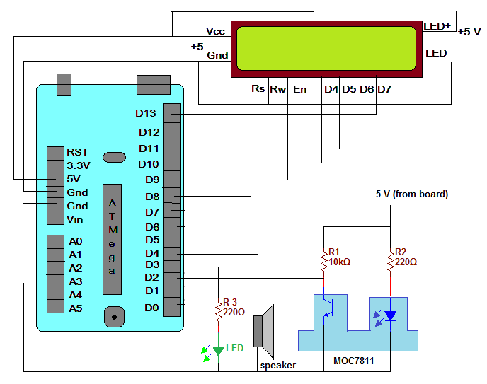
Finds it interesting? Would you like to build this project? Then be ready. Let’s do it. Here is the circuit diagram followed by its description and operation.
Circuitdescription:
As shown in circuit one 16x2 LCD, an LED, one 8Ω speaker and MOC7811 are interfaced with arduino board.
· The Vcc pin (2) and Vss pin (1) of LCD are connected to +5 V and Gnd pins of arduino board respectively to provide it biasing
· LED+ pin (15) and LED- pin (16) of LCD are also connected to +5 and Gnd pins respectively to turn ON LED back light of LCD
· Rs pin (4) and En pin (6) are connected with arduino digital pins 8 and 9 while Rw pin (5) is permanently connected to ground for LCD write enable
· Data pins D4 – D7 of LCD are connected with arduino digital pins 10 – 13
· An LED is connected to pin 3 through current limiting resistor
· One 8Ω speaker is connected to pin 4 as shown
· The internal IR LED of MOC7811 is given 5 V from arduino board through current limiting resistor
· The collector output of photo transistor of MOC7811 is pulled up through 10 K resistor. This output is connected to digital input pin 2 of arduino board after inverting it through transistor Q1
Here is the snap of circuit build on bread board
Circuitoperation:
· The MOC7811 sensor is placed near the door lock in such a way that the latch of lock inserted between the gap of IR LED and photo transistor
· So if the door is properly locked, the latch fills the gap. So IR light does not falls on photo transistor and its output remains high
· Because this output is inverted and given to pin2, the input at pin 2 remains low if the door is properly locked
· So till the input to pin 2 is low, the LCD displays message “door is properly locked”. And the LED is OFF also the buzzer is OFF
· Now as the door is unlocked using key, the latch comes out of the sensor gap and IR light falls on photo transistor
· The transistor conducts and its output become slow
· The pin 2 of arduino gets high input and immediately it displays “door is not properly locked”
· The buzzer gives beep sound and LED turns ON to give audio visual indication of door not locked
· As soon as door is again locked using key, when it locks properly, the sensor gap is again filled and LCD displays same message again “door is properly locked”
So the sensor and circuit arrangement gives a kind of surety it gives indication only when door is properly locked. If somehow if door is not properly locked – the sensor gap remains open that leads to audio visual indication along with message on LCD that door is not properly locked.
Software program andlogic:
The software program is the soul of this project. The program is edited and compiled in arduino IDE software and it is written in arduino C language. The program uses liquid crystal library given builtin in arduino IDE and it checks the status of input pin 2. If it is low means door is locked so it just displays the message. But when pin 2 becomes high, it considers it as door unlocked and turn ON LED, displays message and produce beep sound and it repeats this process continuous. Here is the complete program


_ztBMuBhMHo.jpg?auto=compress%2Cformat&w=48&h=48&fit=fill&bg=ffffff)


Comments
Please log in or sign up to comment.