


Hardware components | ||||||
_ztBMuBhMHo.jpg?auto=compress%2Cformat&w=48&h=48&fit=fill&bg=ffffff) |
| × | 1 | |||
 |
| × | 1 | |||
 |
| × | 1 | |||
 |
| × | 1 | |||
Hand tools and fabrication machines | ||||||
 |
| |||||
What is close loop control system?
Actually, there are two types of controlling system. Open loop control system and close loop control system. First let us see the difference between these two systems with the help of following figure.
As shown in figure, in open loop system the input is directly given to an amplifier. The amplifier amplifies the input and drives the actuator. Actuator is controlled system that gives output. Thus in open loop system the output is totally dependent on input. More the input – more the output and vice versa. There is no any control over the output. In this case it may happen that the output may increase beyond desire limit and that may cause problem. While in close loop system the part of output is taken as feedback and applied along with input. The input and output are compared and it generates error signal. Error signal is difference between applied input and generated output. So until there is deviation between input and desire output, the error signal is generated and applied to actuator through amplifier so output is increased. When desired output is reached the error signal becomes zero and actuator generates desire output continuously.Thus in close loop control system the output is controlled. The system tries to maintain desired and stable output constantly.
The close loop control systems are used in all the industries for controlling different processes. Different sensors are used as feedback to sense output and controller are used to generate desire output. Here the given application demonstrates close loop control system to control light intensity. It uses LDR (light dependent resistor) to sense light intensity and LEDs to vary light intensity. It uses arduino as controller and LCD to display light intensity and other parameters. Let us see the circuit diagram followed by its description and operation
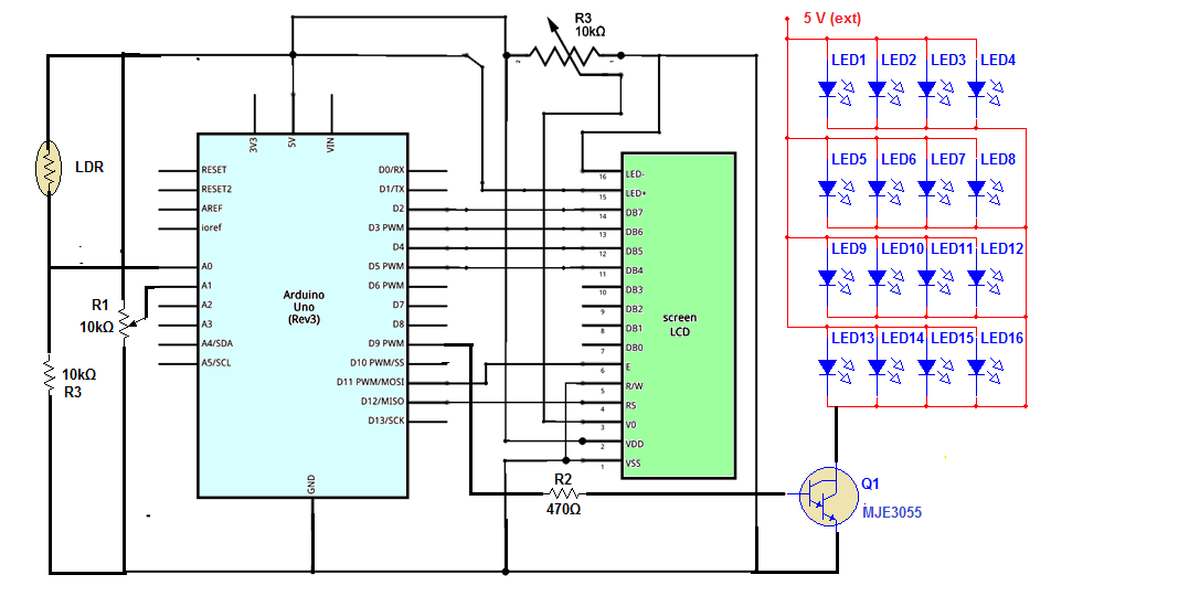
Circuit diagram:1. The LDR is connected in pull down configuration with R3 as pull down resistor. The analog input pin A0 gets input from this junction of LDR and R3
2. Pot R1 is connected to second analog input A1. Its two fixed terminals are connected to Vcc and ground while middle sliding terminal is connected to A1 pin
3. Data pins D4, D5, D6 and D7 of LCD are connected to digital pins D5, D4, D3 and D2 respectively. En pin of LCD is connected to pin 11 and Rs pin is connected to pin 12
4. RW pin is connected to ground
5. A 10K pot is connected to 3rd pin VEE of LCD to vary its brightness
6. LED+ terminal and LED- terminal are connected to 5V and ground to turn on LED back light for LCD
7. The analog output pin 9 drives 16 white LEDs all connected in parallel through transistor MJE3055. Pin 9 is connected to base of MJE3055 through current limiting resistor R2 and the collector output drives all LEDs as shown
8. LEDs are give external 5 V supply and rest of the circuit along with arduino board gets supply from computer USB
Circuitoperation:1. When light falls on LDR its resistance decreases. So the analog voltage at A0 increases and similarly as falling light on LDR decreases its resistance increases. So the analog voltage at A0 decreases. Means the analog output is directly proportional to falling light on LDR
2. Initially when circuit is switched ON, it will start calibrating LDR as per light falling on it for first 10 seconds. The LCD shows message as “calibrating…..”
3. During these first 10 seconds it will calculate max amount and min amount of light falling on LDR and based on that it will set the percentage of light as 0% means min light and 100% as max light. This percentage of light is displayed on LCD as light intensity
4. Pot R1 is used to set threshold value of light below which if light intensity falls then the LED array is switched ON. As the pot is varied from min to max the threshold is varied from 0 to 100%. So one can set any threshold for light between 0 to 100% below which if light intensity falls – the LED array light is switched ON
5. Once the threshold is set, the system continuously monitors light intensity and displays it on LCD in terms of%.
6. If the light intensity falls below threshold, the LED array is switched ON with 20% intensity. The analogoutput means the pulse width at pin 9 is kept 20%. The LCD displays LED light intensity as LED light.
7. Still if light intensity is less than threshold, the LED array intensity is increased by 10% (the analog output is increased) and it keeps increasing till light intensity again increases above threshold level. Once light intensity becomes more than threshold the LED light intensity is maintained fixed
8. Thus the required amount of light can be set with the help of threshold value and the system tries to keep the amount of light more than this threshold by varying LED light intensity


Comments