To start, we need to connect the nRF7002-DK to Visual Studio. Follow these instructions on how to install the software. Once the nRF Connect for Desktop (I'm using v4.2.1), plug in the device into your computer using the IMCU USB port (not the nRF5340 USB port). Turn the power ON (switch near Li-Poly connector).
Ideally, I turn on the device from my phone and the fan starts moving.
The first thing that I did was use the Matter: Light Bulb for the board to see if I could get it up and running and will allow me to turn on and off an LED and then use the pin that goes to the LED to control the fan.
I first opened nRF Connect for Desktop and selected Toolchain Manager.
I opened the latest SDK in VS Code
I selected NRF Connect and selected Browse samples
I searched for matter and selected Matter Light Bulb
This allowed me to open the sample.
Select nRF Connect and select Create Build Configuration at the bottom. Select your hardware, in this case nrf7002dk_nrf5340_cpuapp and select Build Configuration.
This will take a while to run but once it's complete, it will display a "Build Complete" in the bottom right corner.
Once it has finished, go to the Explorer section and right click on the README.rst and copy the path.
Go back to Toolchain Manager and use the drop down to select Bash
Type in cd and then right click to enter the path, removing the Readme section. Put it in quotes so you don't have to manually change the \. For me, it was:
cd "C:\ncs\v2.5.0\nrf\samples\matter\light_bulb"But depending on your version of nRF Connect SDK, the path may be different.
Plug in your device and enter the following commands:
west flash --eraseAt this point, you can commission the device. Depending on your platform, the instructions may vary but you can follow them here.
Now that the device is setup to turn on and off, we can move onto the physical build.
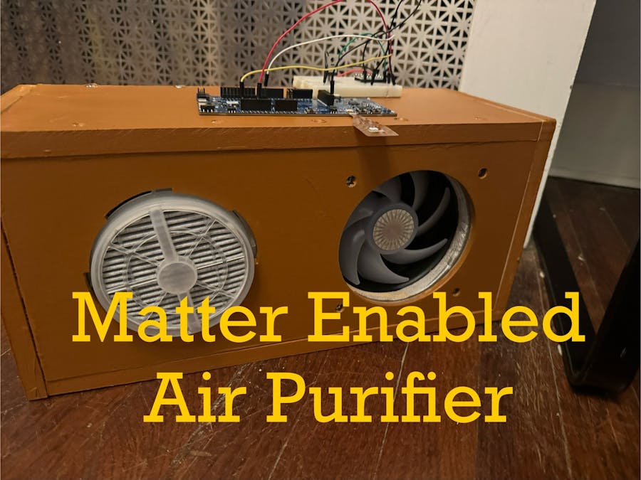
Physical BuildSee the SVG and Carbide3D files. I made everything out of MDF and used my CNC to cut out the two front pieces.
These are the following dimensions
Quantity 3, 14"x6"x0.5" pieces of MDF, one of which is cut using the front 1 layer found in the attached files.
Quantity 1, 14"x6"x0.25" piece of MDF, cut using the front 2 layer found in attached files.
Quantity 2, 6"x7"x0.5" pieces of MDF for the end.
Once cut, paint all of the pieces on both sides. I used brown and silver.
From there, I secured the assembly using wood screws and wood glue, making sure that one of the end was not attached with wood glue in case I need to adjust things internally. There should be a 1/4" gap between front 1 and front 2 to allow the air filter to be
Once completed, the fan can be mounted internally and the filter can be attached to the front. I drilled a small hole in the side to pull out the fan wires. Long term the plan would be to have the nrf7002dk mounted internally but for this test, I thought against it.
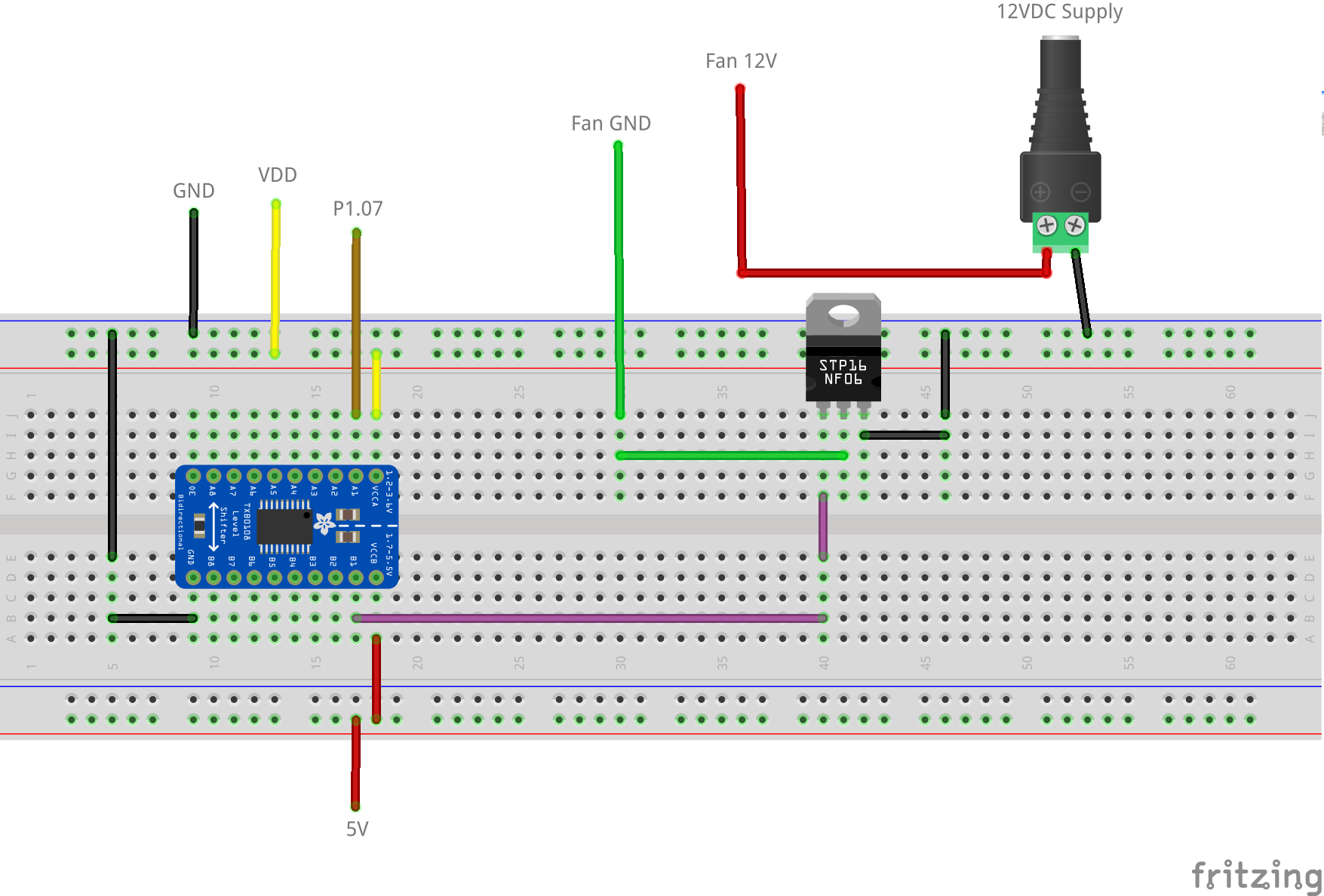
Circuit DesignSo my initial test went ok with the LED turning on from my phone. The problem is that P1.07 outputs 1.8VDC which is not high enough to turn on the IRLB8721 so I need a level shifter. The one that I used was a TXS0108E to allow me to convert the 1.8VDC signal to 5VDC which is within the range to enable the IRLB8721.
See attached for files for the schematic.
Final TestOnce the enclosure is built, the components are installed, the breadboard is connected to the nrf7002-DK and the software is loaded, you should be able to test to verify that the device works from your phone as it does in the video that I took.


Comments
Please log in or sign up to comment.