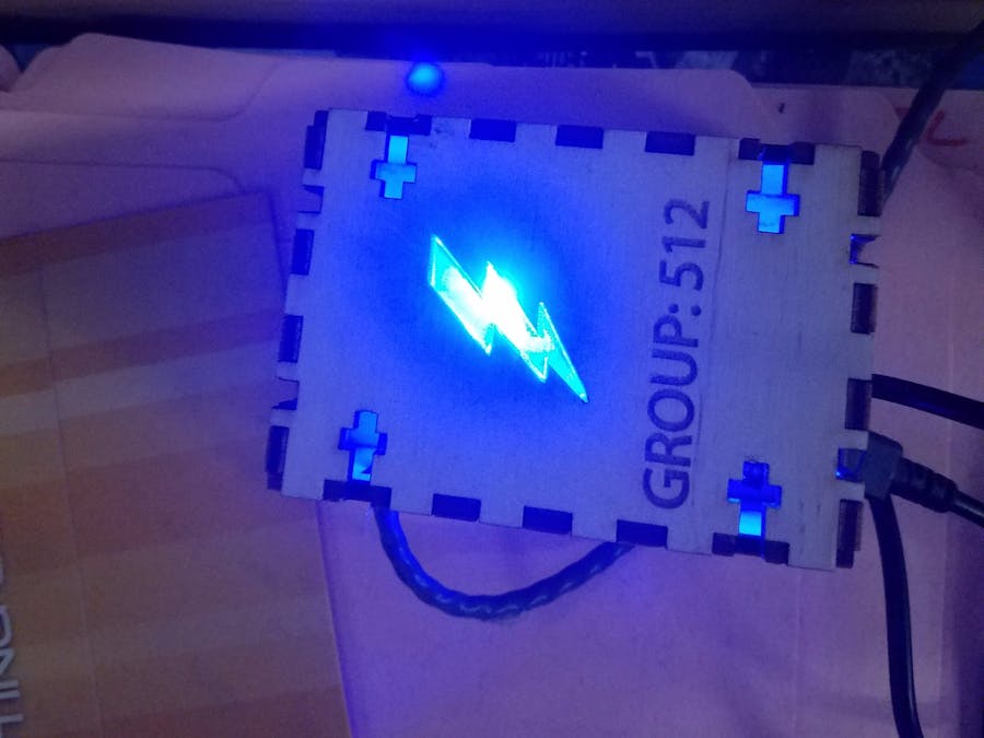
This project is a power and current monitor that can be attached to an electrical live OR neutral wire in a circuit breaker. We chose to make this project because we wanted to find out how much power a single appliance, or if possible, how much power the entire school uses. By doing this, we would be able to see how much energy is being used, when it is used, and how some of it could be conserved. The sensor we used was a Current Transformer(CT) sensor rated at 30 amps, which collects amps and with a few calculations, watts. Through the use of capacitors, resistors, and a photon, the monitor collects and sends data for processing to a Google Spreadsheet. Additionally, depending on the energy level, an RGB LED will change color; red being the lowest and blue the highest.
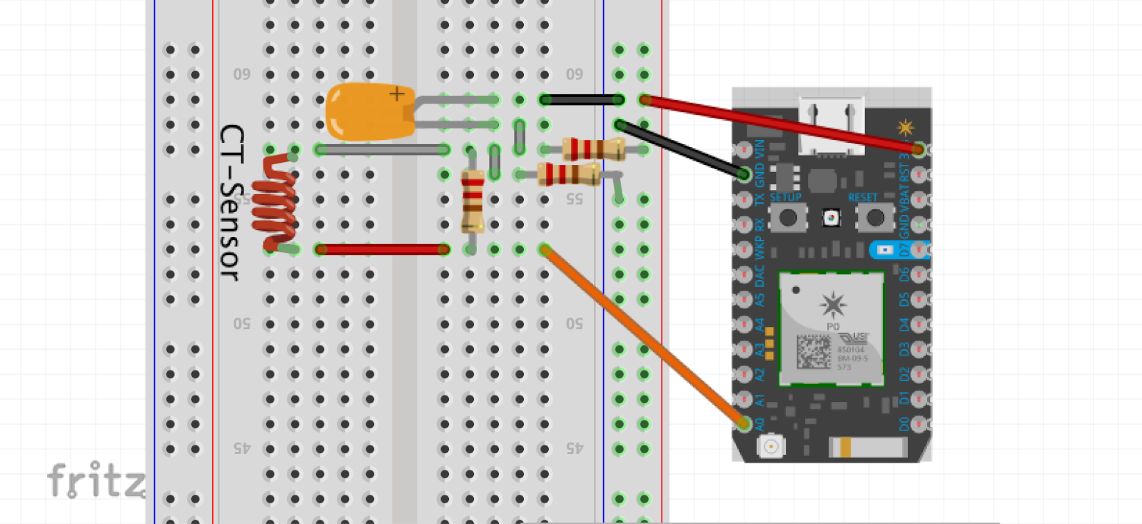
1 / 13 • Circuit diagram's initial brainstorming. Note that the 40ohm resistor was replaced with a 10k ohm resistor.
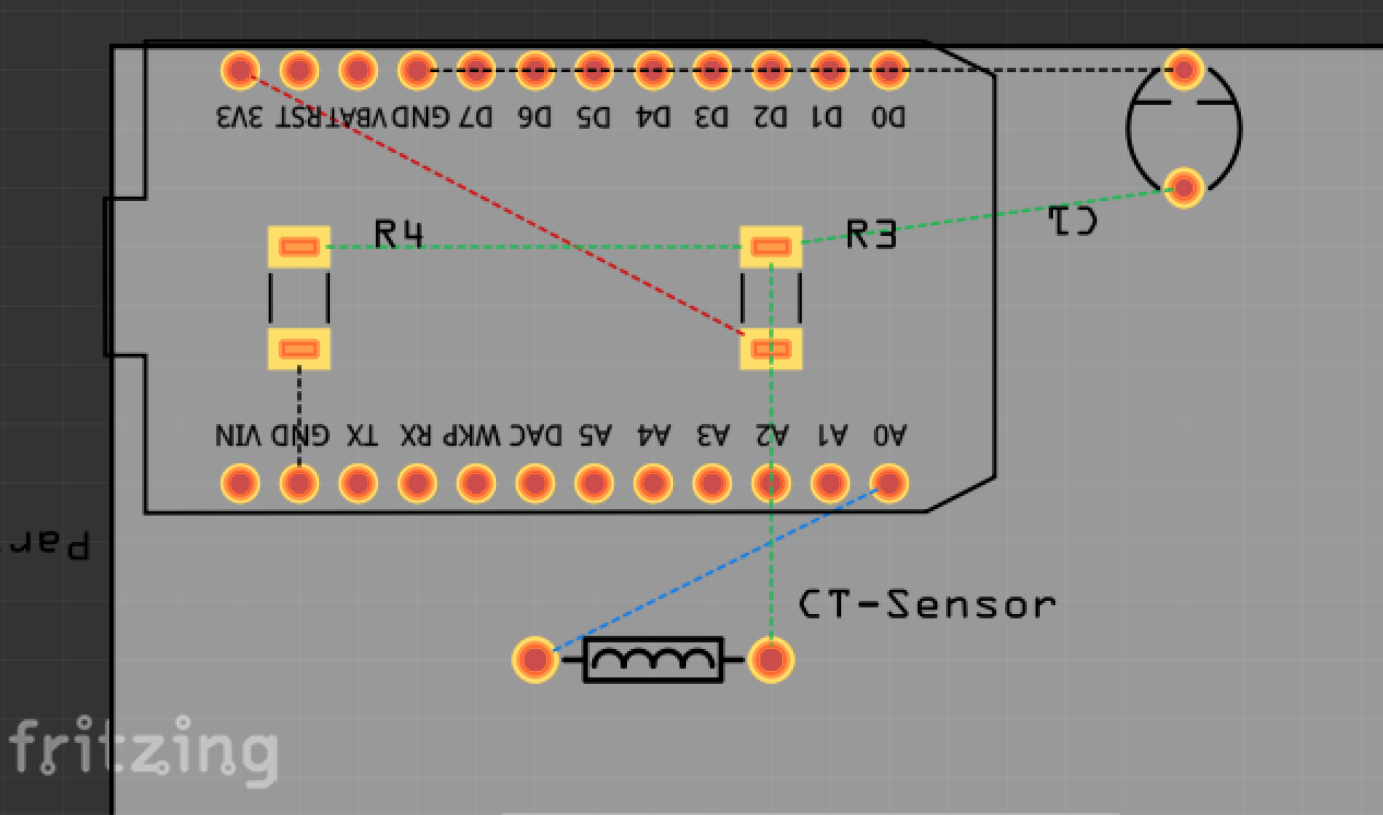
At the start, we researched similar projects to find out what materials we would need and what code resources were already available. We were able to use different parts of each project to help plan our own and we combined the different capabilities to satisfy our needs. On the slideshow above, the process of our thinking and constructing is shown through pictures. If the project should be replicated, see the attached schematics for the breadboard or the PCB design and follow accordingly.
We collected data for over one week and sent it every minute to a spreadsheet. At the end of the time interval, we received over 27,000 data points that we then analyzed, filtered and graphed on multiple timelines to get an idea of what we were seeing and the amount of power the Innovation and Creation Lab at our school uses at different times of the day.
This is a table of all the data collected.
The CT Sensor we used was rated at 30amps, limiting our ability to what we can measure. Our original idea was to measure current draw through the whole school but because of the many circuit breakers in the school, it was hard to choose one that reflects the school accurately. We also faced a tight time schedule and we were unsuccessful in purchasing a CT Sensor rated at 200 amps, which would greatly increase the amount of varying data we would receive. Instead, we received the sensor rated at 30 amps and we decided to measure current draw in a unique classroom, one filled with laser cutters, 3D printers, power tools, etc.
This project WILL be good for home use though as a higher rated sensor means the ability to measure more current. In most US households, 200 amps should suffice for whole building measurement. This also leaves the ability for creative ways of displaying data(such as a live LCD), many of which can be found online or be made up accordingly. If problems arrive, the links we provided seem to be the most informative and helpful in terms of troubleshooting.


_3u05Tpwasz.png?auto=compress%2Cformat&w=40&h=40&fit=fillmax&bg=fff&dpr=2)
Comments
Please log in or sign up to comment.