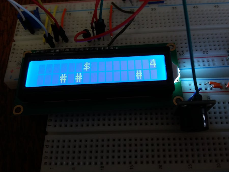
This is a simple LCD game. My inspiration was the Google Chrome's Dinosaur game but I added a few more changes to it. The dollar warrior moves constantly and he can jump to avoid the obstacles and collect the "star" points. If he jumps over the obstacle, he collects one point and if he catches the star, he collects five points. He can also shoot and remove the obstacles in front of him. There are also led diodes which indicate whether he jumps or shoots. When he collects 10, 20 or 30 points he starts moving faster than before. When he collects 50 points, you win. If you hit the obstacle you lose. Of course, you can change these boundaries easily in the code. I also added passive buzzer which makes sound when the warrior jumps or shoots and special melody when you lose or win. This is my first project here and I hope you like it. Give me your comments and reviews.
The videoConnections
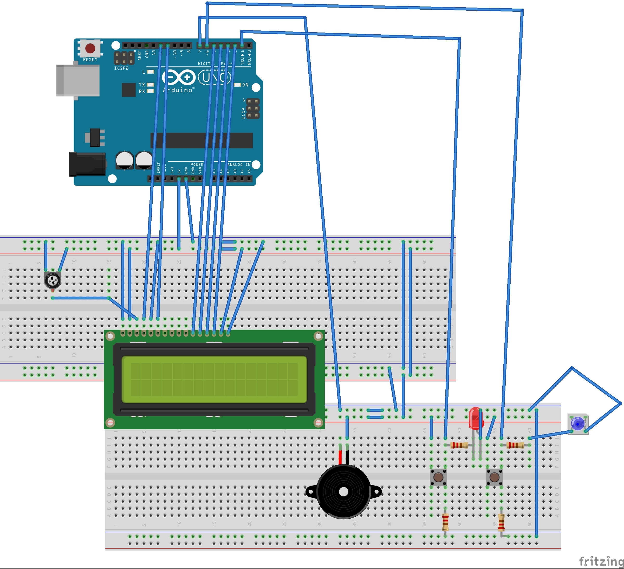
The LCD (Liquid Crystal Display) module has a 16-pin male header on the underside. Plug this into the breadboard as shown in the picture. All of the electronic signals that power and control the LCD go through this header.
These pins are (from left to right):
- GND - power ground signal
- VCC - positive power signal
- V0 - contrast adjust
- RS - register select
- R/W - read/write select
- E - enable signal
- D0 - data bit 0 (not used here)
- D1 - data bit 1 (not used here)
- D2 - data bit 2 (not used here)
- D3 - data bit 3 (not used here)
- D4 - data bit 4
- D5 - data bit 5
- D6 - data bit 6
- D7 - data bit 7
- A - backlight LED positive
- K - backlight LED negative
Use a jumper wire to connect the 5V signal on the Arduino with the red row at the top of the breadboard.
Use a jumper wire to connect the GND signal on the Arduino with the blue row at the top of the breadboard.
- Connect VSS pin to the ground
- Connect VDD pin to the 5V signal
- V0 pin to the potentiometer output pin
- RS pin to Arduino pin 12
- RW pin to the ground
- E pin to Arduino pin 11
- D4 to Arudino pin 5
- D5 to arduino pin 4
- D6 to Arduino pin 3
- D7 to Arduino pin 2
- A pin to the 5V signal
- K pin to the GND signal
Connect remaining potentiometer pins to the 5V signal and the GND signal.
If you have 3 pinned piezo buzzer connect the S pin to the Arduino 7 pin, the '-' pin to the GND and the remaining pin to the 5V signal. If you have 2 pinned piezo buzzer, connect one pin to the GND signal and the other to the Arduino 7 pin.
Connect switch buttons according to the schematics. The first button (jump button) is connected to the Arduino pin 1 and the second(shoot button) is connected to the Arduino pin 6. The leds are controlled only by the buttons and not by Arduino. Anode is connected to the button pin which is connected to the Arduino and cathode is connected to the ground.


_ztBMuBhMHo.jpg?auto=compress%2Cformat&w=48&h=48&fit=fill&bg=ffffff)


_3u05Tpwasz.png?auto=compress%2Cformat&w=40&h=40&fit=fillmax&bg=fff&dpr=2)
Comments
Please log in or sign up to comment.