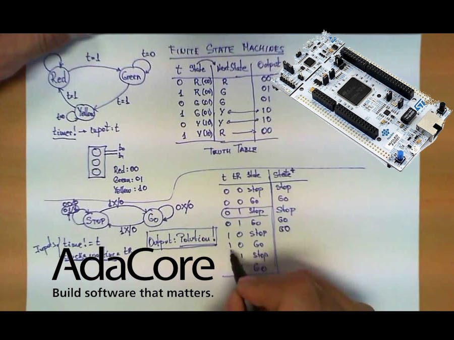
A Finite State Machine, or FSM, is a computation model that can be used to simulate sequential logic, or, in other words, to represent and control execution flow. Finite State Machines can be used to model problems in many fields, including mathematics, artificial intelligence, games or linguistics. FSM is any device storing the state of 'something' at a given time. The state will change based on inputs, providing the resulting output for the implemented changes.
Finite State Machines come from a branch of Computer Science called “Automata-Theory”. The family of data structure belonging to this domain also includes the Turing Machine.
- We have a fixed set of states that the machine can be in
- The machine can only be in one state at a time
- A sequence of inputs is sent to the machine
- Every state has a set of transitions and every transition is associated with an input and pointing to a state
Let’s see what could be a Finite State Machine in the real world:
Coin-operated turnstile
- States: locked, unlocked
- Transitions: pointing a coin in the slot will unlock the turnstile, pushing the arm of the unlocked turnstile will let the costumer pass and lock the turnstile again
Traffic Light
- States: Red, Yellow, Green
- Transitions: After a given time, Red will change to Green, Green to Yellow, and Yellow to Red
A Safe
- States: Multiple “locked” states, one “unlocked” state
- Transitions: Correct combinations move us from initial locked states to locked states closer to the unlocked state, until we finally get to the unlocked state. Incorrect combinations land us back in the initial locked state
Countless front-end developers are still leading a battle against complexity and immobility. Month after month, they've searched for the holy grail: a bug-free application architecture that will help them deliver quickly and with high quality. I am one of those developers, and I’ve found something interesting that might help.
Hence, lets proceed...
Installation & Resources StuffAda was created to target embedded systems about 30+ years ago and by virtue of its maturity has a lot to offer in the area of embedded systems. The potential of Ada comes from its rich type system and expressive syntax that allows to embed a significant amount of business knowledge about what we expect the program to do (in addition to what we instruct it to do) and that additional information can be used to reason about program correctness even before the program is actually executed. Ada is known for its ability to deliver low defect rates - and considering that testing and debugging embedded systems is a very expensive and difficult activity, such language features bring a great added value to the development process.
Considering the positive properties that Ada has with regard to programming embedded systems, its relative absence on the market and even the persistent lack of support from 'many' micro-controller vendors is a curiosity that deserves correction and this project is not even alone nor the first attempt to fix it - the AdaCore company, which is a leading Ada compiler vendor, tries to animate the Ada community with their project examples for the STM32Fx Discovery family of boards. Following this, the community provides with cross-compiler packages that allow to compile and build Ada programs for ARM processors on every major operating system. Alas, I was'nt able to compile that for Xilinx MiniZedtill yet!!
Download the community edition and the ARM_ELF:
https://www.adacore.com/download
For further insights :
https://www.adacore.com/documentation
STM32 driver installation and Ada Drivers Library... as mentioned above
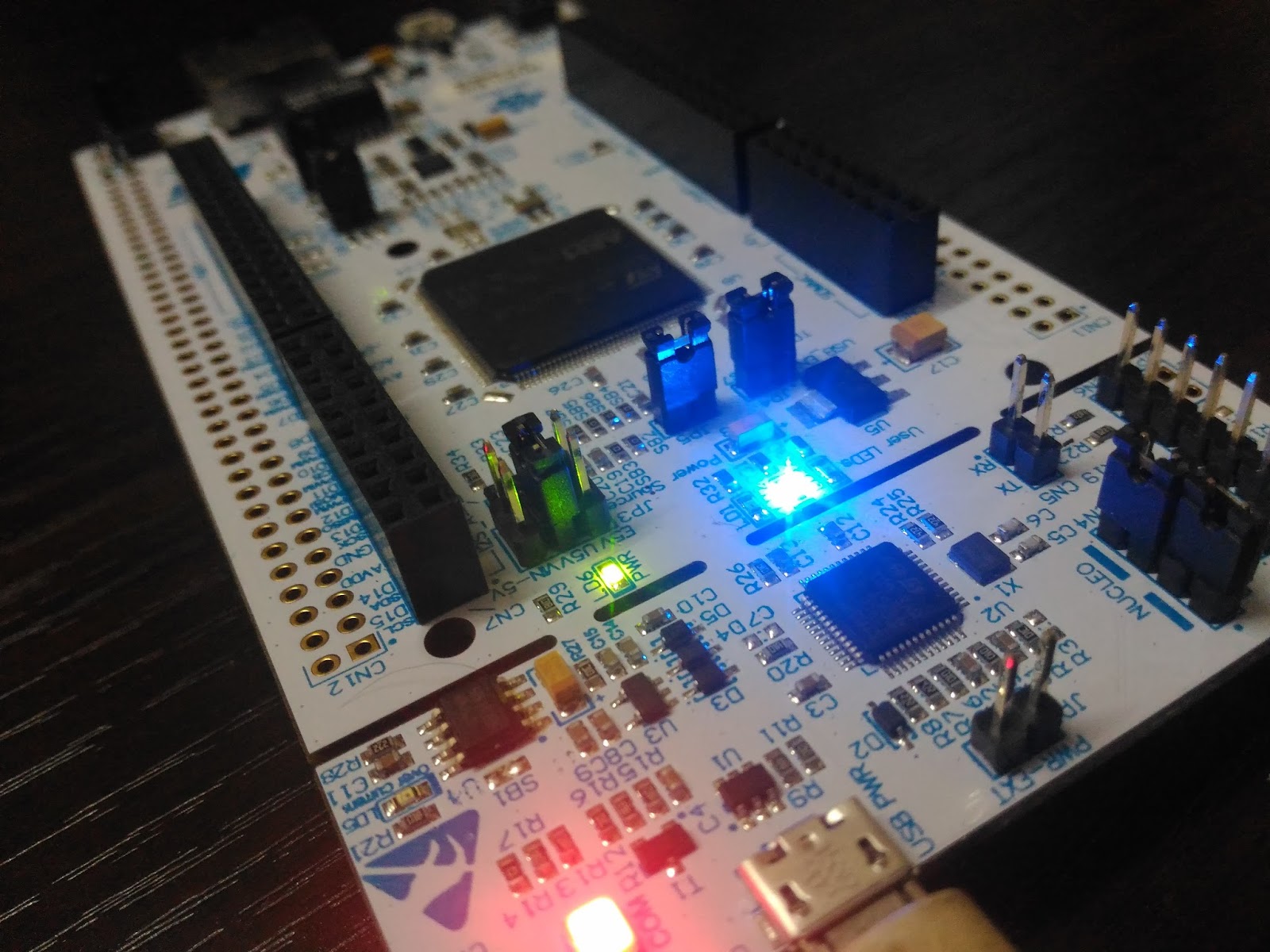
We have build a working ('really') Finite State Machine on Nucleo144, by simulating a basic Fan Control System by hypothesizing, that the fan has the capability to operate in three different modes:
- not moving (stop),
- slow operation,
- medium,
- full speed.
The fan also has two buttons - "up" and "down" - that are used to control its operation. Following;
- when nothing is pressed, the fan continues at the current speed,
- the "up" button switches the fan to faster mode (unless it is already working full speed),
- the "down" button switches the fan to slower mode (unless it is already stopped),
- when both buttons are pressed at the same time, the fan stops, no matter its current speed.
The implementation of this system with our favorite Nucleo is 'bitter' at start, but 'sweet' at the end. I would be using the digital inputs to handle buttons. The pull-up mode is very useful for this, as it minimizes the number of necessary connections - the disconnected pin (reading "high" due to pull-up) will be interpreted as button not being pressed, whereas the pressed button will short the pin to the ground (reading "low", be careful that here the "low" state means that the button was activated, this is also known as the active low configuration). We can also use digital outputs to handle different motor speeds and for the simplicity, I am assuming that there are three distinct control lines that can switch the motor appropriately. The following allocation of pins will be appropriate for this system:
- pin 2 - input mode, handling button "down",
- pin 3 - input mode, handling button "up",
- pin 4, 5, 6 - output mode, switching slow, medium and fast motor speeds when set in "high" state (we can assume that at most one of these will be "high" at any given time).
NOTE: There are several possible strategies for implementing such a system in Ada.
Never ever forget, that the system needs to be aware of its current mode of operation, known as "state", because it is the state, together with the inputs, that influence the decision on what should be done next. Four states have been identified and they can be described in Ada with this enumeration type:
type Fan_State is (Stop, Slow, Medium, Fast);I have also exhaustively described rules for handling buttons - their possible current states (yes, states) can be also described with the enumeration type, similarly to how they are depicted in the diagram above:
type Buttons_State is (None, Up, Down, Both);The Fan_State represents the current activity of the system and is the internal property of the system, whereas the Button_State describes control commands that come from external sensors(simulated).
procedure Control_Motor (S : in Fan_State) is
   begin
      case S is
         when Stop =>
            -- stop the motor
            Pins.Write (Pins.Pin_4, False);
            Pins.Write (Pins.Pin_5, False);
            Pins.Write (Pins.Pin_6, False);

         when Slow =>
            -- first circuit on
            Pins.Write (Pins.Pin_4, True);
            Pins.Write (Pins.Pin_5, False);
            Pins.Write (Pins.Pin_6, False);

         when Medium =>
            -- second circuit on
            Pins.Write (Pins.Pin_4, False);
            Pins.Write (Pins.Pin_5, True);
            Pins.Write (Pins.Pin_6, False);

         when Fast =>
            -- third circuit on
            Pins.Write (Pins.Pin_4, False);
            Pins.Write (Pins.Pin_5, False);
            Pins.Write (Pins.Pin_6, True);
      end case;
   end Control_Motor;

   procedure Read_Buttons (B : out Buttons_State) is
      B_Down : Boolean;
      B_Up : Boolean;
   begin
      Pins.Read (Pins.Pin_2, B_Down);
      Pins.Read (Pins.Pin_3, B_Up);

      if not B_Down and not B_Up then
         B := Both;
      elsif not B_Down and B_Up then
         B := Down;
      elsif B_Down and not B_Up then
         B := Up;
      else
         B := None;
      end if;
  end Read_Buttons;
The Read_Buttons procedure uses reversed logic for interpreting buttons - for example the not_B_Down expression checks if the state read on pin 2 was False, which means that the button was pressed. This is the active low strategy that is a result of pulled-up configuration of the input. With this scaffolding in place, the main program (MainProg.adb) is still a bit lengthy, but has a structure that clearly corresponds to the diagram above;
procedure Run is
      Current_State : Fan_State;
      Buttons : Buttons_State;
   begin

      -- initialize the device
      Pins.Enable_Input (Pins.Pin_2, Pins.Pulled_Up);
      Pins.Enable_Input (Pins.Pin_3, Pins.Pulled_Up);
      Pins.Enable_Output (Pins.Pin_4);
      Pins.Enable_Output (Pins.Pin_5);
      Pins.Enable_Output (Pins.Pin_6);
      Current_State := Stop;
      Control_Motor (Current_State);

      -- repeat the control loop
      loop
         Read_Buttons (Buttons);

         case Current_State is
            when Stop =>
               case Buttons is
                  when None | Down | Both =>
                     -- nothing to do
                     Null;
                  when Up =>
                     Current_State := Slow;
               end case;

            when Slow =>
               case Buttons is
                  when None =>
                     -- nothing to do
                     Null;
                  when Down | Both =>
                     Current_State := Stop;
                  when Up =>
                     Current_State := Medium;
               end case;

            when Medium =>
               case Buttons is
                  when None =>
                     -- nothing to do
                     Null;
                  when Down =>
                     Current_State := Slow;
                  when Up =>
                     Current_State := Fast;
                  when Both =>
                     Current_State := Stop;
               end case;

            when Fast =>
               case Buttons is
                  when None | Up =>
                     -- nothing to do
                     Null;
                  when Down =>
                     Current_State := Medium;
                  when Both =>
                     Current_State := Stop;
               end case;
         end case;

         Control_Motor (Current_State);

         Utils.Waste_Some_Time;
      end loop;
   end Run;
The above strategy of implementing finite state machines relies on the source code structure to reflect the design and rules of all state transitions. This approach has the advantage that the logic of the program is encoded in its statements and this makes it easier to understand when following its line-by-line execution in the debugger. On the other hand, the state transitions are entangled with the code and are more difficult to replace with other transition patterns by means of a simple re-configuration. In any case, the above code does not contain any elements that would be hardware-dependent. The necessary, even though very simple, Hardware Abstraction Layer (HAL) is already provided by the Pins.adb with support from Registers.adb and Utils.adb
ConclusionThrough this article, we saw what a Finite State Machine is. We saw that a Finite State Machine is a model of computation based on a 'far more practical' machine made of one or more states and only one single state of this machine can be active at the same time. The designed nascent-FSM system based on Ada worked well to our expectations and would likely to challenge once again with a question..
Can Turing Machine be deployed on STM32 through Ada..!!as done by Cambridge University guys :
https://www.cl.cam.ac.uk/projects/raspberrypi/tutorials/turing-machine/


_9nsOFQ7ama.png?auto=compress%2Cformat&w=48&h=48&fit=fill&bg=ffffff)


Comments
Please log in or sign up to comment.