


Hardware components | ||||||
 |
| × | 1 | |||
 |
| × | 3 | |||
 |
| × | 1 | |||
 |
| × | 1 | |||
 |
| × | 1 | |||
| × | 1 | ||||
| × | 1 | ||||
 |
| × | 1 | |||
 |
| × | 50 | |||
 |
| × | 1 | |||
| × | 1 | ||||
| × | 1 | ||||
Software apps and online services | ||||||
| ||||||
 |
| |||||
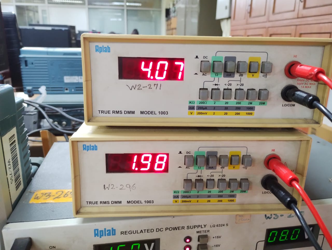
I developed this project as a part of my work at WEL Lab, IIT Bombay. It is a simple analog square root circuit that calculates the square root values of a DC input signal up to an accuracy of 98 percent. It uses log and antilog amplifiers to implement a mathematical function that imitates the required function.
As far as the schematic is concerned, it is a 5 stage circuit.
1st stage (developed using IC-741) - Variable Unity-gain Buffer. The input DC signal is fed to the integrated circuit, via a 10k potentiometer. As we vary the slider of the POT, the input voltage changes, and as a result, the output voltage changes symmetrically. This variable DC input is fed to the main circuit.
2nd Stage - Logarithmic Amplifier
3rd Stage - Offset Cancellation Stage (It shifts the voltage by a fixed DC level, nullifying the offset error due to the log stage.
4th Stage - Gain Inducing Stage (It provides a gain of 1/2 to the incoming voltage signal with an inverting amplifier)
5th Stage - Anti-Logarithmic Amplifier (It calculates the inverse log of the input and provides the final value)
Final Working Diagram -
Stage - Wise Mathematical Calculation:
Log - Amplifier Stage
Now, one of this design's most important aspects is ensuring that the diodes used in the log and anti-log stage are working in the linear region. So, we need to check the ln(Id) vs Vd characteristics of the diode and then, select suitable resistors to ensure its proper operation.
For the diodes D1 and D2 in the working diagram, the characteristics were plotted using Matlab and it is as follows -
3rd, 4th and 5th Stage
I have attached a document with all my calculations. Pls, make sure to check it before conducting this experiment.
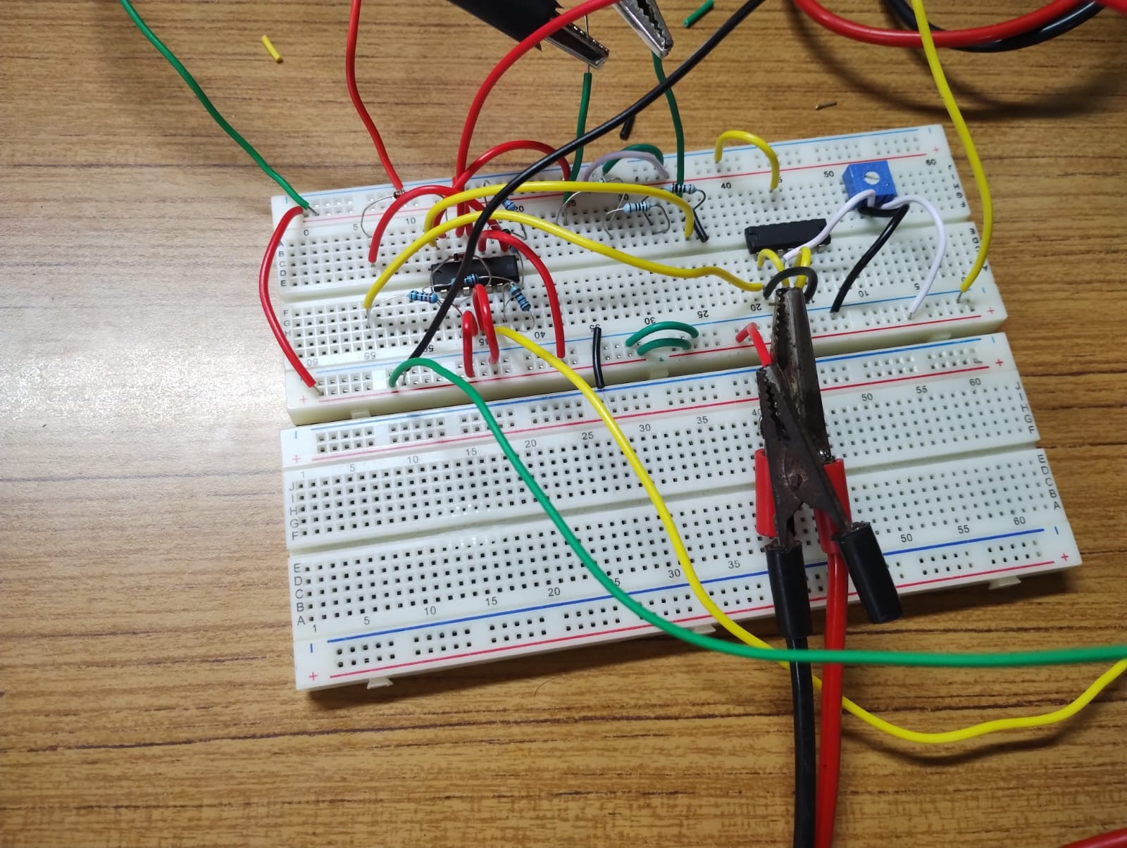
Actual Circuit Blocks


Comments
Please log in or sign up to comment.