


Hardware components | ||||||
 |
| × | 1 | |||
 |
| × | 1 | |||
 |
| × | 1 | |||
 |
| × | 1 | |||
| × | 1 | ||||
 |
| × | 1 | |||
 |
| × | 2 | |||
 |
| × | 1 | |||
Software apps and online services | ||||||
 |
| |||||
 |
| |||||
| ||||||
| ||||||
| ||||||
| ||||||
| ||||||
| ||||||
Hand tools and fabrication machines | ||||||
 |
| |||||
 |
| |||||
 |
| |||||
| ||||||
| ||||||
| ||||||
 |
| |||||
| ||||||
| ||||||
| ||||||
Initially this was started as a little fun project, simply to frustrate a friend, however it has been so much fun its worth sharing!
What we wanted was a take on the classic "Talkie Toaster" from the TV Show Red Dwarf, which would be able to constantly ask toast related questions every time someone was nearby. We also wanted it to respond to being shouted at as well, so we added a few more parts to the project.
It was also a chance to try out our PCB Etching, but this could be assembled on a breadboard / strip board just as easily.
In the future we will further integrate it with other IoT peripherals and services, and this tutorial will get us well on our way...
General HardwareTo achieve this project we needed a wide array of hardware, anything marked with a (*) can be omitted unless you are trying to build the project in its entirety.
SoundAs our project is all about the sounds we need to convert them into a format we can use on our Arduino with our chosen library (TMRpcm).
All sound encoding can be done reliably using Audacity.
If your tracks are stereo you will need to downmix them to mono (as we only have one speaker) using the option on the Tracks > Mix menu.
Now Export the file from File > Export > Export As WAV, and ensure the bit rate settings are as below:
Save all of these new files to your SD Card, and if they run as part of seperate conversations, naming them in a "conversation_StepId.wav" can be useful to make them easier to iterate in the code.
CodingTo code this was relatively easy as there is already an WAV compatible library for the AVR platform, and so all we need is to add in our logic, and the code for reading our microphone and PIR sensors.
In the code we:
- Setup all I/O
- Work out what conversation to start in
- Wait for a trigger to begin a conversation (PIR Only)
- If talking to someone, wait for a response (MIC) before responding with the next segment
- If no-one responds after a period - give up and go to the start of the next conversation for the next person
To create the circuit board we used here, we used a 3D Printer along with a 2.5w UV Laser.
- Paint the copper clad board with a single layer of black matt paint
- Design the Gerber files in a tool of your choice (Free PCB, Eagle, etc..)
- Export your Gerber in Black and White, where Black represents the paint / copper to remove, and either vertically or horizontally flip the bottom copper layer
- Open Inkscape and resize the document to fit your printer bed
- Ensure you have the JTech laser tool installed
- Import this into Inkscape and resize to the correct size
- Convert the Image to Path using the Edge Tracing Tool
- Use the JTech Laser tool to generate the laser GCode
- Run on Printer
Now you should have a board which resembles the below:
This needs a scrub with a soft bristled brush, and we have found doing this dry first, then using a little washing up liquid works well. Clean until the copper is visibly shiny again.
NOTE - If this doesn't work you may need to tweak your laser settings to be slower / higher power.
Now we can place the board into our Ferric Chloride to etch away the copper, putting your phone torch under the vat can be useful to see progress, as the light shines through the board where the etching is progressing.
NOTE - remove the board after 5-10 minutes and gently scrub the tracks again. This ensures any paint which was not fully removed now is as the acid weakens the edges of the remaining paint.
Once the etching is complete, rinse off the board, and if you're happy remove the rest of the paint using acetone.
Now we can drill the holes for our components using a small drill, 1 mm in this example (be careful not to break the bits!)
NOTE - there were a few copper areas I failed to join on the PCB so a few added holes and wires were put in to correct this (see second image above)
We have used no solder mask or tinning solution in this project. I will just lacquer the board when finished to prevent corrosion as its just a fun project.
Now just cut the board to size and the fun really begins!
Populate the BoardNow we can add all our components to the board, and solder them in place. As we have no solder mask or tin on our board we need to ensure any flux residue is removed post soldering (acetone or warm water), so we left our board to dry overnight....
We realised we had missed a resistor at this point, but its on the Nano itself so we added it now between D2 and D9. This gives us controllable feedback for our lights.
Now we can solder our LEDs together, and add wires to them, and to our speaker. Then solder the other ends to the relative connections on the board
The Black lead is due to a soldering fail on my part, the board tracks are there for this!
The CodeAt this point we just had to put the code together to make all of this work as expected, and this is included in the files at the bottom.
Rename any WAV files or pin assignments depending on your implementation.
Try it out at this point, its far easier to fix before its attached to a toaster!
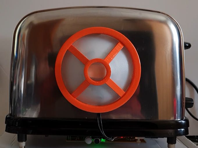
The Other Physical PartsAt this point we wanted to attach ours to our toaster of choice, and add a speaker cover fitting of the project, so we 3D Printed a cover, and spray painted it (didn't have any orange plastic).
We used an old plastic milk bottle to cut out the windows, and super glue to attach them to the speaker cover.
Then gluing some magnets on the back meant it would stick to the toaster, but could be removed from the toaster easily if needed.
Then we just attached our speaker and LED inside using a double sided foam pad on the back of the speaker, to the centre of our cover.
Some sticky foam pads allowed us to attach the board to the bottom of the toaster, giving the final toaster!
Useful Links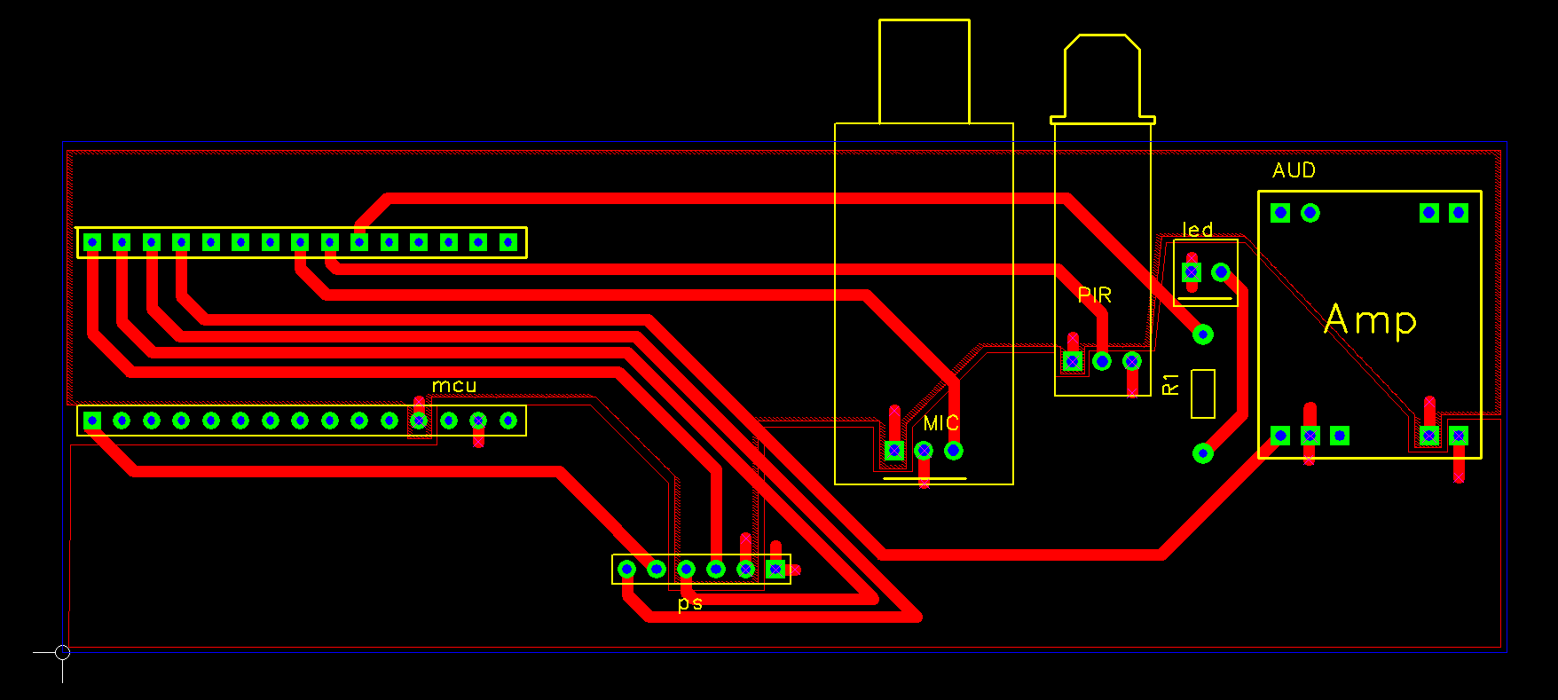


_3u05Tpwasz.png?auto=compress%2Cformat&w=40&h=40&fit=fillmax&bg=fff&dpr=2)
Comments
Please log in or sign up to comment.