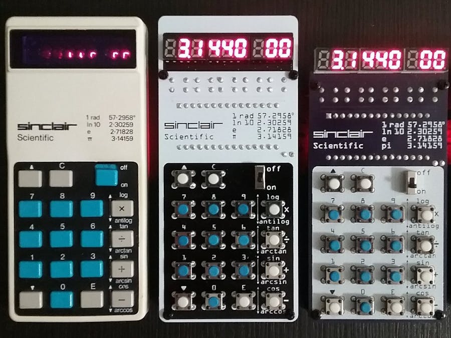
Understanding the architecture of past, simpler CPUs is important to learn how to create future devices.
This project implements an accurate emulation of the Sinclair Scientific Calculator. Most of the display glitches are accurately duplicated. The components in this project are easily sourceable, thus it should be able to be replicated.
The original chip inside the Sinclair Scientific Calculator was reverse engineered by Ken Shirriff, its 320 instruction program extracted and an online emulator written. This project ports that emulator, written in Javascript, to the Arduino Nano and interfaces it to a custom PCB. The result is an object that behaves like the original calculator, with its idiosyncrasies and problems. Calculating PI as arctan(1)*4 yields a value of 3.1440.
Special care was taken in the design of the emulator to match the execution speed of the original calculator, which varies from acceptable to atrocious for trigonometric functions involving small angles.
DetailsThis project documents how to turn a web page into a functioning physical object. It has a hardware and a software side.
The software side of this project is a port to the Arduino platform of the original Sinclair Scientific Calculator simulator (http://righto.com/sinclair).
The hardware part has evolved over time. It started as a quick modification to the Kim UNO by @Oscarv (http://obsolescence.wixsite.com/obsolescence/kim-uno-summary-c1uuh) with the keys arranged in the Sinclair pattern and a 9 digit display.
Over time, the PCB has evolved, over two iterations the width has been reduced to match that of the original calculator. The keyboard on the latest version is dimensionally accurate. Its keys line up with the buttons on the real calculator.
By experimenting with a real Sinclair Scientific calculator, the connections between the keyboard and the display digits were deduced. An accurate schematic has been created, its correctness verified by pressing simultaneously multiple keys on the calculator and observing that the display glitches in the same way in the original and the emulator.
This has turned the V5 and V6 PCBs into the most accurate emulators out there.
The V5 PCB is limited in height to 100mm so it can be manufactured inexpensively.
The V6 PCB has the same accurate keyboard and display circuit as V5 and is also dimensionally accurate at 110 x 51mm.
A version using bubble LED displays is in the works depending on the continued availability of those modules.
Open Source Licenses:
The original TI / Sinclair simulator is licensed under GPL v2 so the Arduino port is also licensed under GPL v2
The PCB files are:
Sinclair Scientific Calculator Emulator by @ArduinoEnigma is licensed under a Creative Commons Attribution-ShareAlike 4.0 International License.Based on a work at http://righto.com/sinclair.
Step 1
On the front side of the board, install the blue pushbuttons on the number keys and the white pushbuttons on the rest of the keys. Flip the board over and while putting pressure to ensure all the buttons stay fully inserted, solder the whole keyboard.
Step 2
On the back side of the board, install the 8 LED display current limiting 1K resistors on the spaces labeled R1 through R8, just below the display.
On the back side of the board, Install the keyboard 4.7K resistors on the spaces labeled KR1 through KR3.
Flip the board over to the front and solder the resistors.
Step 3
Depending on the version of the board, the displays are placed too close together. To make them fit, sand down the b, c, d, and e sides of the displays. Consult the diagram below:
[a DS1 b] [c DS2 d] [e DS3 f]
Install them in the front, flip the board over and solder them.
Step 4
Flip the board over to the back and insert the Arduino Nano. Ensure the usb connector faces the word USB printed on the PCB.
Flip the board over and solder all the pins. Be careful to not touch the displays or the keys with the hot iron while soldering the Arduino.
Step 5
Download the Sinclair Scientific Calculator sketches and libraries from here:
Upload the sketch to the Arduino Nano.
This sketch has a display self test feature. By pressing 0 while the Arduino powers up, the display will show all the digits lighted up. If 8 is pressed while all the 8 are lit, a longer display self test will be shown. Pressing C at any time will take the calculator to its home screen.
Step 6
Flip the PCB to the front and install the power switch. Flip the board to the back and solder it.
Step 7
Flip the board to the back and solder a 4 AAA battery pack to the terminals labeled VIN + -. Be careful with the polarity. As a strain relief, put a drop of Loctite Go2 Gel or hot glue on the back of the board where the power cables are soldered.
The battery pack can be attached to the PCB with 2 sided sticky tape. Add Go2 Gel for increased strenght.
Step 8
Install 4 M2 standoffs on the four holes provided on the PCB.
FilesV5 Schematic.png: V5 Schematic. Download gerbers athttps://oshpark.com/shared_projects/OSfM0RLN
This project is available for purchase at our Tindie Store:
https://www.tindie.com/products/ArduinoEnigma/sinclair-scientific-calculator-emulator/


Comments
Please log in or sign up to comment.