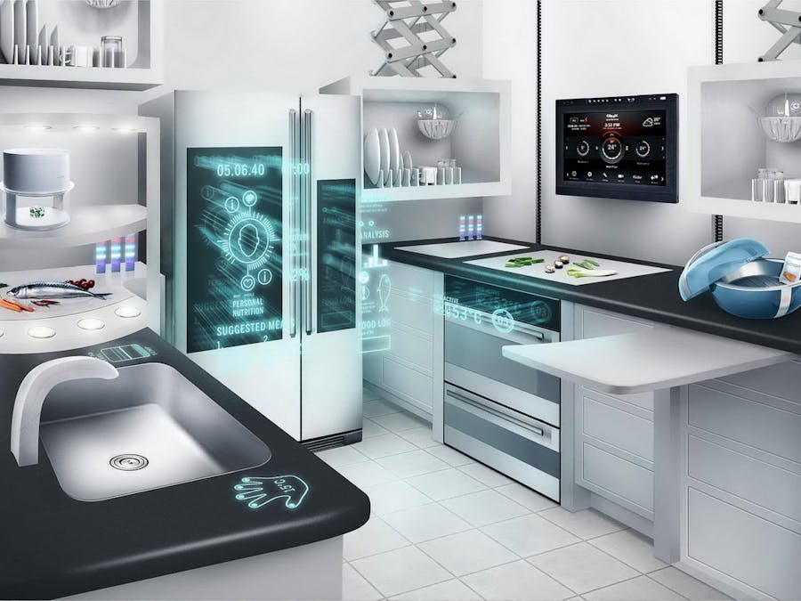
I was planning to build a cheap home automation system. I want this to be a modular system so that I can keep adding sensors and devices to it without much changes. WARAN (Windows IoT, Azure, Raspberry Pi, Arduino, NRF24L01+) is a modular home automation system with consists of a single Hub and multiple modules. The module will combination of micro-controller and sensors collecting data from different locations of the house and transmitting the data to Hub via RF. All the communication between Hub and modules happens via RF. There will be a companion windows phone app for the Hub as well. Here is a simple flow diagram explaining the setup.
Why Windows IoT ?
I am a software developer currently venturing into IoT. With my previous experience with XAML/C# and Visual Studio (which I consider to be the best IDE ever) it was very helpful for me to implement these very quickly.
Why NRF24L01+ ?
When I was looking into wireless options NRF24L01+ came up as a cheap and low power consuming solution. With some really powerful libraries available it came us a best solution for me.
Why Windows Azure
Windows Azure very easy to learn and adapt. With little configuration required to bring up the service we can focus more on development rather than configuration and deployment. My previous experience with Azure helped me in quick integration.
The Hub
The Hub is a center controlling center of WARAN. It is made up of RPI2, Arduino Uno and nRF24L01+. The RPI2 runs Windows IoT core. It runs a Universal App which acts as the control center. The Hub would be connected to a large display (typically a TV or monitor) via which we can see the data from the modules and also control the modules. A keyboard and mouse connected to the RPI2 will help in adding, removing modules from the control center. Here is the circuit diagram of it (Refer WARAN.Hub.fzz. file in project)
How it functions ?
Every module will have a unique address using which the hub communicates with it. We will add a module to the control center using this address and giving a name to the module. Once added the control center (Universal App) will send data to Arduino Uno via I2C. Arduino Uno will send data to the module via nRF24L01+ and the module reads data from the sensors or start/stop a device based on the data it received and sends data back to Arduino Uno. The Arduino Uno will send the data to the control center via I2C. This data which will be displayed in the TV/Monitor and also sent to cloud. The Arduino Uno will just act as an interface for RPI2 to get the sensor data from other modules. The above process will happen in three scenarios
- At specific intervals depending on the module
- When user interacts with control center (via Mouse/Keyboard)
- When a trigger is sent from the cloud (vis PubNub)
Here is a typical flow
And this is how components in the hub and modules interacts between them.
The Control Center
The control center is a universal app running in the RPI2. The control center is the interface for the user to interact with. It communicates with the modules and also with the cloud. WARAN control center utilizes Azure Mobile Services and PubNub as its cloud back-end. Every module info we add will be stored locally in sqlite db and also sent to azure mobile service. This will in turn send a PubNub message or push notification to mobile app. I don't want to explain the coding part here and make this article a mess. The project source code, documentation and deployment details can be found in https://bitbucket.org/arjunganesan/waran (I am in the process of updating the documentation fully which will be done soon). This is how the control center works
The Mobile App
The mobile app is a windows phone app (will be developing for other platforms later) which will act as a companion app to the hub. We can see all sensor related data in the mobile anywhere from the world. If in case of any important information is got from the module (like a alert for gas leak from a gas leak monitor module) we will get a push notification as well. Also we can trigger some action on the module (like starting a pump on the Plant Waterer module) from the mobile itself. Since all these happens via cloud there is not need for a mobile device to be present anywhere near the hub to do all these action.
Here is how the Mobile App looks
Modules
The module is combinations of components working together and receiving and sending data to and from Hub via RF. It can be a combination like Arduino Pro Mini with sensors or RPI2 with sensors etc. All it needs to do is receive the data/command from the hub via RF and respond appropriately. This give a infinite possibility of modules. To get started I am adding 2 modules
- Plant Waterer
- Temperature Monitor
WARNING: All the modules here are configurable to control electrical devices using relay. But I don't have experience handling those so I didn't want to meddle in the danger zone so I haven't used it in my project yet. Those who have good experience in handling the relay please feel free to extend the circuit, others please take proper precaution if you want to work in it.
Plant Waterer
The plant waterer will monitor the water level in the plants and also temperature in the environment around the plant. In case there there is no sufficient water an alert will be sent to the mobile app. We can start the pump from the mobile app from anywhere. We can also configure it to automatically start the pump whenever the water level goes below threshold. Its consists of Arduino Pro Mini, DHT11, Soil Hygrometer, and nRF24L01+. Here is the circuit diagram (Refer PlantWaterer.fzz in the project)
The power from 9V battery goes to RAW pin of Arduino Pro Mini. The inbuilt voltage regulator in arduino will give 5V output in Vcc. We will use this to power DHT11. Also we give the 9V power as input to 3.3V voltage regulator which we will use to power nRF24L01+. The water level from the hygrometer will be read on the analog pin A3. The temperature reading from the DHT11 will be read in digital pin 6. In digital pin 5 we will send a signal to a transistor or a relay using which we start stop a pump. For demo purpose I will use a DC pump and will use a transistor as switch. And here is the flow of how it works
I didn't want the circuit to remain in breadboard so I transferred it to a perfboard. I want to keep it compact so i made it this way. You can refer the circuit diagram and come up with your own layout.
And below is a video on how it works.
Temperature Monitor
The temperature monitor will monitor the temperature in a room (e.g. bed room) and keeps up posted on the temperature and humidity level. Also we can switch on/off or adjust a device (Thermostat, AC etc.) from the hub or mobile. For demo sake I will switch off/on a LED connected to the arduino. The circuit consists of Arduino Pro Mini, DHT11 and nRF24L01+. Below is the circuit diagram (Refer TemperatureMonitor.fzz file in project)
The power from 9V battery goes to RAW pin of Arduino Pro Mini. The inbuilt voltage regulator in arduino will give 5V output in Vcc. We will use this to power DHT11. Also we give the 9V power as input to 3.3V voltage regulator which we will use to power nRF24L01+. The temperature and humidity reading from DHT11 will be read in digital pin 5. In pin 6 we will send a signal to a transistor or a relay using which we start stop a device (eg. Thermostat, AC etc.). For demo purpose I will use a LED light to show switching off/on of the device. And here is the flow of how it works
Here is how I laid it in a perf board . You can come up with your own layout based on the circuit diagram.
And here is how it works
Known Issues
- Power - The battery drains within few hours in both the modules. Need to find a efficient and portable power source. I am planning to use attiny processors in place of pro mini in whichever modules possible. It would be more efficient on power. My previous articles on attiny can be found here.
- I2C Concurrency - If RPI2 send 2 wire request to Arduino uno at a time then one of them fails. I am working on a way to avoid this and also trying to implement a retry mechanism.
- One Way Communication - Right now the Hub initiates a request and the module responds for it. Though this works well on many scenarios some new modules may require to send data to Hub without the hub sending a request.
- Range - I have kept the modules in the next room and able to receive data properly. But if you want to increase the range replace the nRF24L01 in Hub with NRF24L01+PA+LNA which has a external antenna.
- Security - Since this is developed on a assumption of being owned by the developer I didn't add any authentication mechanism. If you want you can utilize the Identity service of Azure Mobile service to integrate Microsoft, FB, Twitter, Google authentication to the mobile app and the hub.
Future Plans
I would like to make this as a open platform for people to implement their own home automation system. I will be stabilizing the Hub and the Mobile app. I would like to add many more modules to this project. Voice based command and response is in the road map as well. Right now I am working on the below modules
- Gas Leak Sensor
- Intrusion Detector
- Device Controllers (eg. Coffee machine Controller, Light Controllers, etc)
- Garage Door Opener
- Some Wearable Modules
- Internet Services without hardware (Weather, Azure Logic App, Stock Report etc)
- Modules that works outside of Hub's range and communicate with it via internet (e.g. Car tracker, Pet Tracker, Pedometer etc.)
All these modules combined together and working as a single unit via Hub will give me the home automation system I always wanted to have. I will be keep adding the new modules as separate projects in hackster. Everyone is welcome to add new modules and expand. Will be updating the wiki page on how to add new modules to the project.


_ztBMuBhMHo.jpg?auto=compress%2Cformat&w=48&h=48&fit=fill&bg=ffffff)


Comments
Please log in or sign up to comment.