(This project is being managed here: Project Repository )
Introduction:The heart rate monitor is used to measure heartbeats in a minute. It can be useful in many applications like health and fitness. For those who go for workouts daily, it has been easy for them to keep track of their moves and steps with the help of this device. To maintain good health it is important to do the exercise at some target heart rate. This will help in achieving a better health recovery. Heart rate is a crucial factor in identifying how intense your workout is. If you are over-exerting during a workout your heart will alert you by telling your heart rate through this device. There are two ways by which heart rate can be measured:
- Manual way i.e. by counting the number of pulses passing through a wrist
- Automatic detection i.e. a sensor that will automatically count the heartbeats
The manual way is not efficient in measuring the heart rate because there are more chances of human error in it while a heart rate monitor is more efficient to keep the track of the number of pulses passing through a heart during training.
Working:In this project, I have designed a heartbeat monitor. This module consists of LDR(Light-dependent resistor), and LM358. The LM358 is a transducer amplifier which means that it will take the electrical signals from your heart and will convert them to digital signals in the form of pulses. Whenever a pulse will be detected this module will turn on the LED. This modulated light is received by the light detector. In LDR, when light falls on the resistor, its resistance changes. As the light intensity increases, the resistance decreases. Thus the voltage drop across the resistor decreases. The LM358 has a comparator that compares the output voltages to threshold voltages. If the output voltage is higher than the threshold it means the intensity is high and vice versa. This is how this device measures the intensity of your workout.
Specifications of LM358 Op Amplifier:This IC consists of two high gain amplifiers. The reason for using this IC is that it does not require another independent power supply for the working of each comparator. For a single power supply, It provides input voltages from 3V to 32V while for a dual power supply it provides voltages from 1.5V to 16V. It has a DC gain of 100dB.
This IC consists of two input power supplies and one output supply in a comparator. It provides a wide range of power supplies.
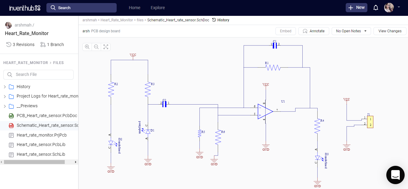
Schematic Diagram:I have implemented my design on Altium designer. After creating a new project, I have designed the symbols and footprints of each component in a schematic document. In the center, there is an op-amp i.e. LM358, and a header on the left side for battery terminals. Below is the schematic diagram of my design.
I have created my design online on Inventhub where all my design files are available. You can find my project files on Inventhub.
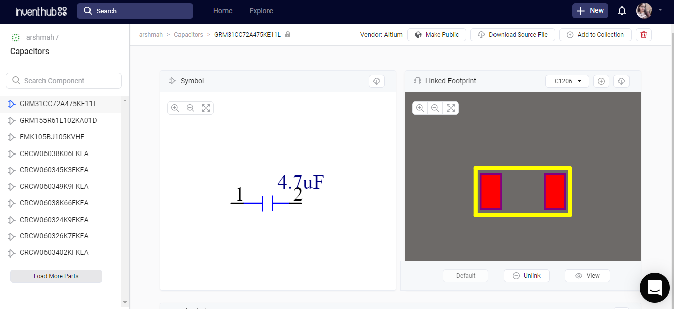
While designing the PCB board it is important to take care of the footprint and dimensions of each component. Footprints should be exactly the same as per component size otherwise your design will not be perfect. To avoid this inconvenience, I have shared all my component's symbols, dimensions, and footprints online on Inventhub. I have categorized them differently and I can reuse them in my next design. I have created of collection of my components for a PCB design. The list of components used in this project is available on Inventhub.
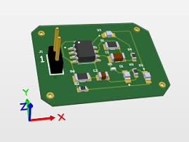
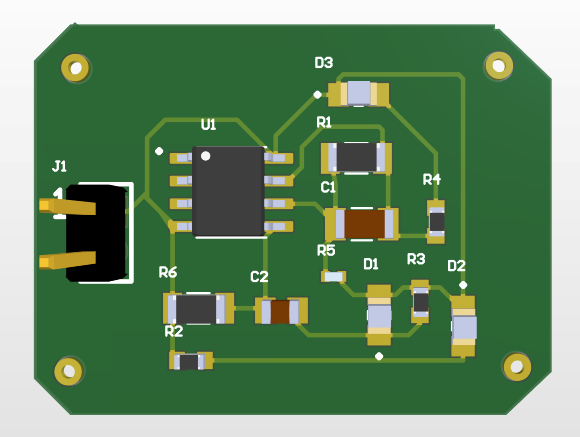
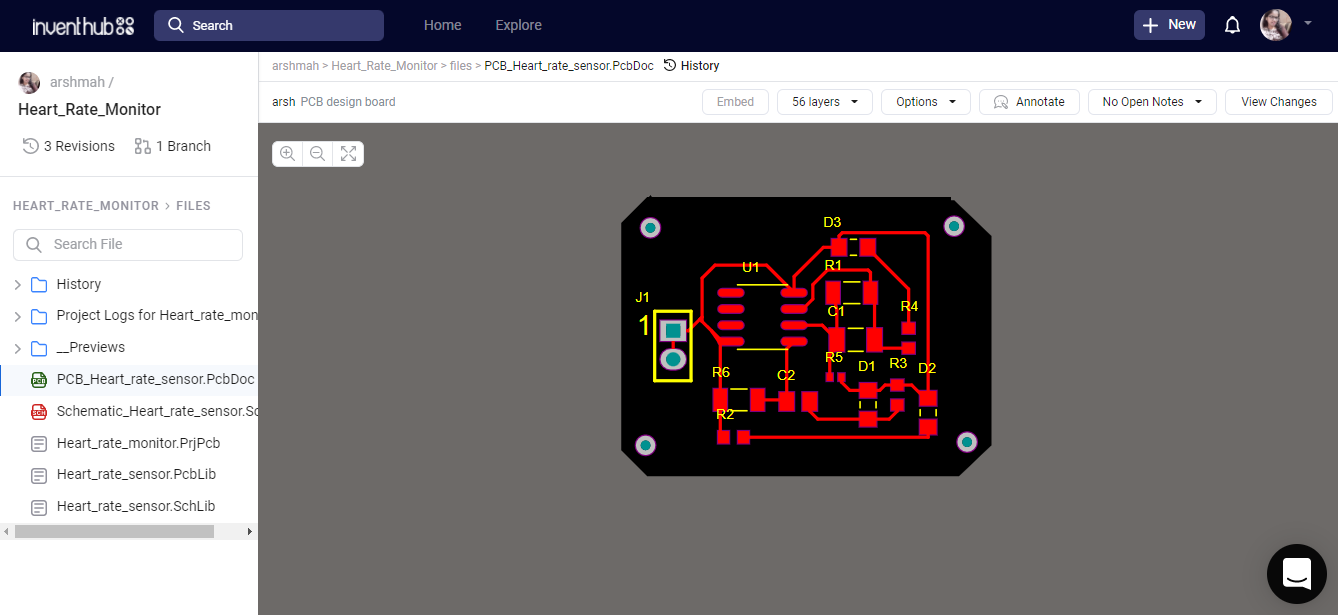
After creating the design in the schematic, I have converted it to the PCB. Where I have designed my board with a specific size and dimensions. This includes the routing of the board on different layers. At this part, I can view the 3d model of my board.
On Inventhub you can find my PCB file of the project.
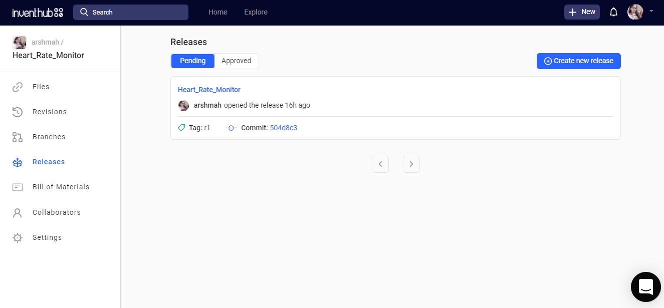
Design for ManufacturingAfter designing the schematic of the board I need to fabricate it from the manufacturer. For fabrication instead of visiting the manufacturer, I will share my project files with him through the online platform Inventhub. I have created a release of my project that consists of all the design files in a zip folder. The manufacturer only needs to export the file and he can fabricate the board without any error.
Here the release of my project is available on Inventhub.
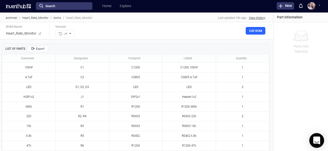
Bill of Materials(BOM)When I will get my fabricated board then I need to embed components on it. For this, I have created a Bill of Material(BOM) on Inventhub which consists of all my component's details with exact footprints and dimensions. He will only export the file and will get the details of the components. This will help me get the same component as I have used in my design.
This is the link where my.CSV file of components is available on Inventhub.
Looking forward to your feedback. Feel free to ask any query at arshmah@inventhub.io






Comments