


Hardware components | ||||||
 |
| × | 1 | |||
 |
| × | 1 | |||
 |
| × | 1 | |||
 |
| × | 1 | |||
 |
| × | 1 | |||
| × | 1 | ||||
| × | 1 | ||||
| × | 1 | ||||
Software apps and online services | ||||||
| ||||||
 |
| |||||
 |
| |||||
Hand tools and fabrication machines | ||||||
 |
| |||||
 |
| |||||
 |
| |||||
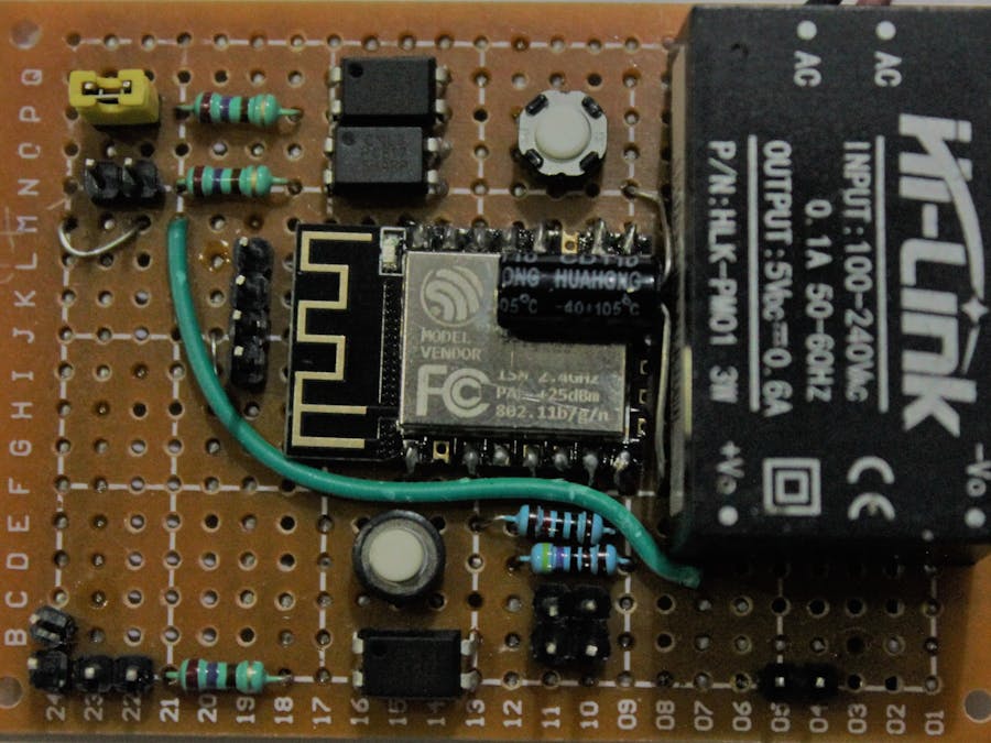
Make a smart switch using the ESP-12F module for two-relay control + motion detection using PIR sensor. Motion detection is selectable. If it's enabled, then relay two will operate based on PIR sensor. PIR sensor enable/disable is possible via MQTT message.
- 1: 230V to 5 VDC SMPS
- 2- 5VDC to 3.3 VDC voltage regulator
- 3: ESP-12F
- 4: Opto-couplers PC817
- 5: Passive components (resistors, capacitors)
- 6: Male & female pin headers and screw terminal
- 7: Push Buttons
- 8: Two-channel relay board (5VDC operated)
- 9: Raspberry Pi 3B+
- 10: 16GB class 10 SD card
- 11: HDMI to VGA converter
- 12: 5VDC 2.5 Amp power supply for Raspberry Pi
- 13: PIR sensor
Concept: This PCB can be easily installed into a conventional switch board without changing any hardware like switches or wiring schemes.
Basic Design: This PCB operates two relays. Operation is possible by two methods: first is via hard wired switches and second is through MQTT DASH Android App. Relay two can operate using PIR motion sensor.
ESP-12F Wiring: The module is 3.3V operated and field wiring is at 5VDC. To protect the ESP, PC817 opto-couplers are used. Optocouplers convert 5VDC to 3.3VDC visa versa.
ESP-12F to Relay Board Wiring: Relay board operates at 5VDC, so PCB needs to be modified. Remove LED on each relay and sort its two pins. Aafter this modification, the relay works fine with 3.3VDC. Relay coil is 5VDC rated and ESP output is 3.3V so you need to remove short link provided on relay board without fail.
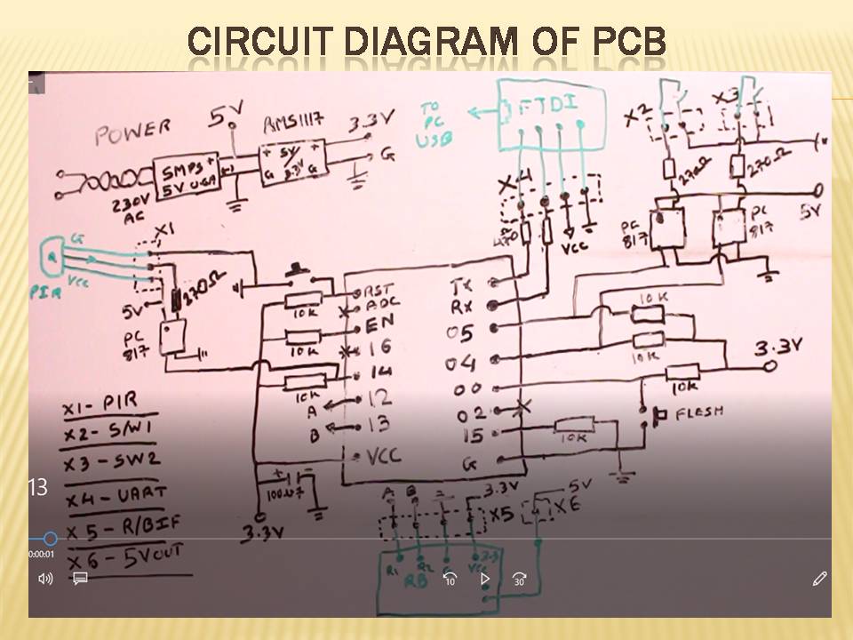
Field Connection: Different pin headers are provided for field wiring.
- X1: for to connect PIR sensor.
- X2: to connect switch 01.
- X3: to connect switch 02.
- X4: to Program ESP module.
- X5: to connect relay board.
- X6: to proive 5VDC to relay board.
Circuit Diagram: Below is detailed circuit of PCB.
ALL About ESP-12F: I made an all-in-one document for ESP-12F that shows each pin detail and function of each pin. This PIN guide is suitable for all ESP8266 modules.
Raspberry Pi Setup:
Raspberry Pi B3+ used. 16GB ScanDisk SD card used with Raspbian OS. Raspbian image download link: https://downloads.raspberrypi.org/raspbian_full_latest. After download Raspbian image, unzip it and store on desktop (or suitable place). To write image on SD card, download Eatcher. Eatcher link: https://www.balena.io/etcher/
- Run Etcher and select Raspbian image (unzipped image only)
- Select appropriate SD card and press flesh button and wait till process completed.
- Then remove SD card and insert into Raspberry Pi. To setup Pi, you required 5VDC 2.5A power supply (original Raspberry Pi power supply adaptor prefereds) HDMI to VGA converter (in case HDMI monitor, only HDMI cable required) keyboard and mouse.
- Once Pi boots up, connect it with Internet via Ethernet cable or WiFi. I used WiFi as I have a routher running at my home.
- Once Internet is connected, open terminal window and apply
sudo apt-get updateand hit enter. Once update process is completed, applysudo apt-get upgradeand hit enter. When prompted Y/N, hit Y, press enter and wait untill upgrade process completed. Both of the above processes take a minute, depending on your Internet connection.
Installation of Mosquitto Broker: Open terminal window and apply sudo apt install -y mosquitto mosquitto-clients and press enter. This will install two components: the Mosquitto broker and Mosquitto client. When system prompts Y/N, press and hit enter and wait until process completed.
Checking of MQTT BROKER: To check MQTT broker, open Terminal window and apply mosquitto -v and hit enter. The system will show version of Mosquitto broker once you get response as mentioned below. Window apply hostname -I and press enter, system will respond with IP of MQTT broker (IP of Pi) as per the image below.
Mosquitto Broker Checking: For this, open two terminal windows.
- In one window, apply
mosquitto_sub -d -t testTopicand hit enter. This means we subscribed on topic name "testTopic" and client publish on "testTopic" will be shown in this window. - In the second window, apply
mosquitto_pub -d -t testTopic -m "Hello world!""mosquitto_pub" means publish and text in between "__" is value which will published on topic "testTopic." So when we hit enter, we get "Hello world!" in first window (as per image below). If you get same response then MQTT broker is working and we can move further to set up Android app.
Android App:
- Open Google Play Store and search for MQTT DASH app, then install that app.
- Link: https://play.google.com/store/apps/details?id=net.routix.mqttdash&hl=en_IN
- Open MQTT Dash and click + symbol at right top corner.
- Only two fields require name: "Any unique name you like" and enter IP address of MQTT broker.
- After entering above settings, click on generated connection and if you get blank screen then connection is successful. If your mobile is not on the same network on which MQTT broker is running, you get "connecting" message with running circle. In that case, make sure your mobile is on same network on which MQTT broker is running or not.
- Create sample text publish field: now add new entry field (text) and enter topic "testTopic" and not requried any other setting to change.
- Enter any text and hit send button. If you get that text on Raspberry Pi terminal window, then your MQTT connection is successful.
Final Setup: Finally add two buttons, one for relay one and second for relay two. In topic field of both buttons, we need to copy topic text from the Arduino code.
Final Trial: Finally check system by clicking motor one > relay one turned on and visa versa. I have installed this PCB in switch board. Connect two switches with X2 and X3 and relay one and two connected to lights.
Warning: Working with 230VAC is unsafe. Only qualified people are permitted for that.
For more details, I kindly ask you to check out the YouTube video.


Comments
Please log in or sign up to comment.