


Hardware components | ||||||
| × | 1 | ||||
 |
| × | 1 | |||
| × | 1 | ||||
| × | 6 | ||||
 |
| × | 3 | |||
 |
| × | 1 | |||
 |
| × | 1 | |||
 |
| × | 1 | |||
_ztBMuBhMHo.jpg?auto=compress%2Cformat&w=48&h=48&fit=fill&bg=ffffff) |
| × | 1 | |||
Software apps and online services | ||||||
 |
| |||||
Hand tools and fabrication machines | ||||||
 |
| |||||
Have you ever felt as if your common lock was too boring to use? Just multiple numbers with no actual grandeur and now you're looking for a new option? Well, look no further! The Arduino Colour Lock is here to help. This revolutionary lock uses colours instead of digits to place lock for your product.
I created this project as a fun way to experiment with the Arduino and this is the first-ever project I have done with it. The project utilises the fastLED library which is used to control and easily manipulate a variety of RGB led lights like the NeoPixels. This Project took time to think up but I got it after I thought of important uses these addressable LEDs could have. A lock it was.
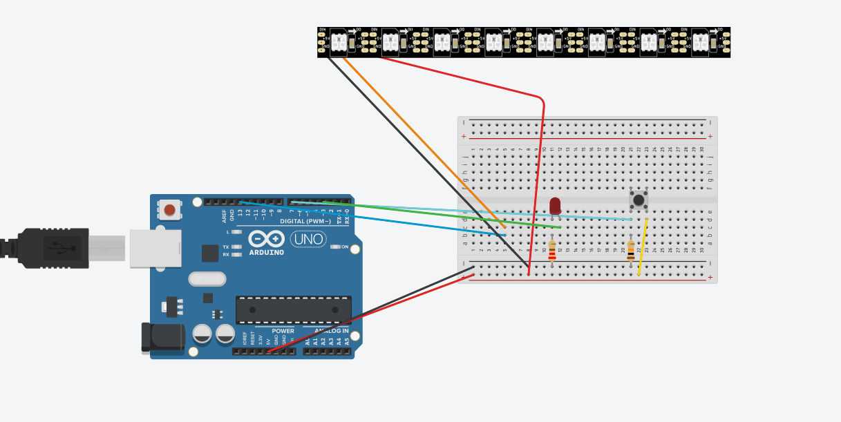
Step 1 - Building the circuit.First, get all the materials you need. It should look like this.
Grab your breadboard, 2 male/male jumper wires and your Arduino UNO. Connect the jumper wires to the 5V and GND pins on your Arduino. Then plug the other end of the 5V wire to one of the + pins on the breadboard and the GND wire To the - pin next to the other one. This is what it should look like.
When you have done that connect a button in towards the middle connecting over the bridge in the centre. Make sure that you are only one pin into the bridge on the side you have your other wires.
After, connect one male/male jumper wire into pin 7 on your Arduino and connect the other side of it in front of the left side pin of the button. Connect another wire from a positive side of the rails (The last 2 rows of the breadboard) 2 pins in front of the right pin of the button. After you have done that you connect a 10k resistor (brown red black black brown) from the negative rail into the pin behind the lift side jumper wire you connected originally.
Now you can add the LED strip. First, put a wire connecting to pin 13 on the Arduino and connect the other side to a free slot on the half of the board you are using. Connect the female sides of the female/male wires into the soldered pins one in DI, GND and another in the 4-7 DC pin. After that has been done connect the male end into the breadboard with the DI pin next to the pin 13 wire and put the GND onto the negative rails and put the 4-7 DC wire into the positive rail just as you had done in the beginning.
Finally, time to add the green LED. Connect a wire to pin 3 on your Arduino. connect that to an empty space on your breadboard. Connect a 220 resistor from the positive rail to the pin slot next to the pin 3 wire. One pin above of where you put it put your LED with the longer pin next to the wire and the shorter pin next to the resistor.
Now you have finished the circuit. I also have a CAD model of the circuit down below. You can move this into any casing you want (obviously if you can fit it).
How I made this circuitI took inspiration from one of the circuits I had seen my friend building, a simple one with an led. I stretched out bits of it and added the LED strip to it. It wasn't a hard circuit to make but I think you should be able to do it. If you don't understand how a Half Breadboard works then look here for more info.
https://www.sciencebuddies.org/science-fair-projects/references/how-to-use-a-breadboard
Step 2 - Getting the code.The code is down below and you can test your circuit out.
How to change your colours
Go to this line in your code and change the values for each of your colours. You can experiment with the colours you want. The only catch is that the values must be less than or equal to 225 and there have to be 3 values, RGB. To get specific values you can go to this website and change the colour by changing the values that it says to change to.
https://www.rapidtables.com/web/color/RGB_Color.html
You do the same if you want to change your actual lock, with the colours you had set above. It is in this line.
The code was difficult to do even though had already planned it out with a flow chart.
This is what I wanted to happen in my code. But I ran into a problem. I didn't understand the library I had chosen. Do I had to learn everything from scratch, with nearly no help from anyone. In the end, I don't even know if it works because my actual led broke. If it does then I got really lucky but I want you guys to try it out and see if you can fix any errors in it.
The Ledstrip looks for values it is given to mixing the Red Blue and Green to get any colour on the spectrum.
Next, I developed the case as a 3D model using the TinkerCad software. Unfortunately at this time, I did not have access to 3d printers so I wasn't able to make it but I have attached the 3d printable file above the circuit schematic if you would like to try it out.
It is hollow on the inside.

Comments
Please log in or sign up to comment.