


Software apps and online services | ||||||
 |
| |||||
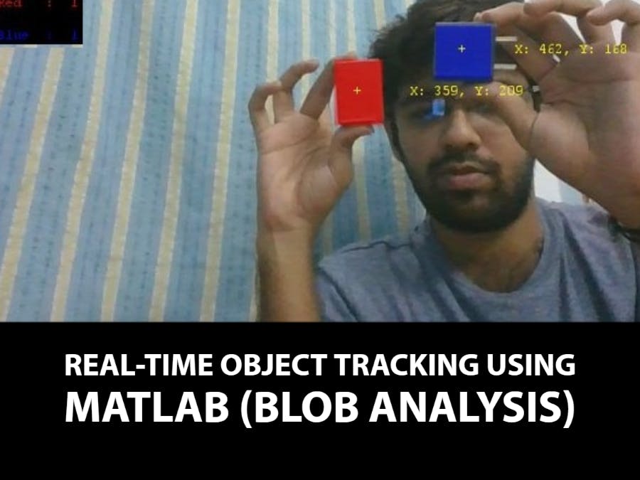
A machine vision-based blob analysis method is discussed in detail. The centroid value of an object is calculated from the image captured. The centroid value represents the location of the object in the workspace with respect to the image frame. In this work, red and blue objects are identified from the workspace.
Blob Analysis is a fundamental technique of machine vision based on analysis of consistent image regions. This tool is a choice for applications in which the objects being inspected are clearly discernible from the background. The main advantage of this technique to analyse an image includes high flexibility and excellent performance.
A blob is a group of connected pixels in an image that shares some common property (grayscale value). An example of Single blob and Multiple blob is shown in the below image. The white connected regions are blobs. The goal of blob detection is to identify and mark these regions.
The basic scenario of the Blob Analysis solution consists of the following steps:
1. Extraction – The RGB image is obtained as shown and it is converted into a Grayscale image with a threshold value. The threshold (0 to 1) is applied to obtain a region corresponding to the objects (or single object) being inspected as shown. In this example, red coloured objects are going to be detected.
2. Refinement – The extracted region is often flawed by the noise of various kind (due to inconsistent lighting or poor image quality). In the refinement step, the image is enhanced by applying a noise filter (median filter). The median filter is a non-linear digital technique used to remove noise from an image. Fig. 3.5 shows the output after applying the filter. After applying the noise filter, the image is converted into a black and white image with a red threshold. Fig. 3.6 shows the output with only red components.
3. Analysis – In the final step, the refined image is converted into a binary image and the final results are computed. If the image contains multiple objects, it is split into individual blobs each of which is inspected separately.
A bounding box is drawn over the blob. A Bounding Box of a blob is the minimum rectangle which contains the blob as shown. It is defined by finding the four pixels with minimum x-value, maximum x-value, minimum y-value and maximum y-value. From these values the width of the bounding box is given as xmax – xmin and the height as ymax – min.
Once the blobs are detected and the bounding box is drawn over it, the centre of the blob (object) must be calculated as it represents the location of the object in the workspace.
The centroid (centre of mass) of a physical object is the location on the object where you should place your finger in order to balance the object. It is the average x- and y- location of the binary object. It is defined as a point, whose x-value is calculated by summing the x-coordinates of all pixels in the blob and then dividing by the total number of pixels. Similarly for the y-value. Mathematically, the centroid (x, y) of a blob (object) is calculated as in the below equation.
where N is the number of pixels in the blob. xi – yi is the x and y coordinates of the pixels respectively.
SoftwareIn this work, Matlab 2016a is used. OS Generic Video Interface hardware Support Package must also be installed.
In order to check whether the camera device, either your inbuilt webcam of the laptop or your externally connected camera is configured in Matlab, type the following statement in the command window and hit enter.
>> imaqhwinfoThe imaqhwinfo function returns information about all image acquisition adaptors available on the system. The output should be something like shown below.
>> imaqhwinfo
ans =
InstalledAdaptors: {'winvideo'}
MATLABVersion: '9.0 (R2016a)'
ToolboxName: 'Image Acquisition Toolbox'
ToolboxVersion: '5.0 (R2016a)'
Here, winvideo is the inbuilt webcam of the laptop. That's it. All set to go! Copy-paste the code from the Code Section and Run the same in Matlab,
MATLAB Output


Comments
Please log in or sign up to comment.