


Hardware components | ||||||
| × | 1 | ||||
| × | 1 | ||||
Software apps and online services | ||||||
 |
| |||||
In this project, the time, date and the latest headlines are to be displayed as a ticker on an LED matrix. Date and time are to be updated from a time server.The headlines are received from a so called RSS feed. This is a service offered by various web servers such as tagesschau.de. This service uses http or https as transmission protocol, but the data is not delivered in HTML format as usual, but as XML, i.e. without layout information.
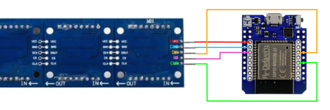
CircuitThe LED matrix is simply connected to the SPI bus of the ESP32. The data output of the ESP32 MOSI (GPIO23) is connected to DIN of the matrix. The clock output of the ESP32 CLK (GPIO19) is connected to the clock input of the matrix. The GPIO16 of the ESP32 is used as chip select, it is connected to the CS connector of the matrix. The matrix is supplied with 5V, this is no problem for the ESP32, because all connectors used here are used as output and therefore cannot get higher voltages from the matrix.
In addition to the ESP32 package, you need four libraries.We use the library TinyXML to extract the desired information from the received XML data. The library has only three functions.
void init (uint8_t* buffer, uint16_t maxbuflen, XMLcallback XMLcb);This function is called in the setup function. The parameter buffer points to a byte array to hold temporary data, the parameter maxbuflen specifies the size of the buffer. The parameter XMLcallback points to a callback function
void XML_callback(uint8_t statusflags, char* tagName, uint16_t tagNameLen, char* data, uint16_t dataLen)
which is called whenever an XML element has been completely processed. The statusflags parameter specifies which data is provided. Since we are interested in the content of an XML tag, we will only use the status STATUS_TAG_TEXT. The tagName parameter points to a character array containing the full XML path to the item. For the title of an item of the newsfeed, this is then the path "/rss/channel/item/title". The tagNameLen parameter returns the length of the path. The parameter data also points to a character array containing the data. The last parameter dataLen returns the size of the data array.
void reset();This function resets all internal pointers. It should always be called before new XML data is read in.
void processChar(uint8_t ch);This function sends one character of the XML data to be processed to the XML parser. This function must be called sequentially for each character received. If the transmitted character leads to the completion of an XML block, the callback function is called with the corresponding data. The LG_Matrix_Print library is used to display strings on the LED matrix. The following functions are used in the sketch:void setEnabled(bool enabled); Access to the LED matrix is enabled or disabled.
void setIntensity(uint8_t level);This function changes the brightness of the display. Values between 0 and 15 are allowed. Normally 1 is quite sufficient
void display();The content of the display memory is transferred to the matrix and thus visible.
void clear()The display memory is cleared.
int printText(int start, String text, boolean isUTF8 = true);This function converts the string specified in the text parameter, starting with the nth character, into the corresponding bit pattern in the display memory using the internal character set. The character at which the output should start is specified in the start parameter. The optional parameter isUTF8 switches the internal code converter on or off.
void ticker(String message, uint16_t wait);This function makes it possible to implement a ticker very easily. The parameter message points to a string containing the text to be displayed. The second parameter wait specifies the time in milliseconds to wait before the text is advanced by one pixel. The library takes care of everything else.
boolean updateTicker();This function must be called in the loop function to update the ticker.
The library contains other functions, but they are not used in this sketch.The WebConfig library is used to configure the WLAN access data as well as other settings via a browser. The configuration is stored in the flash file system SPIFFS and remains even after the microcontroller is switched off. A detailed description can be found at: https://github.com/GerLech/WebConfig/blob/master/README.md or in my book Smarthome.
The WebConfig library requires the Arduino_JSON library, so this must also be installed, but is not included in the sketch.
The sketch
#include <LG_Matrix_Print.h> //Bibliothek für die Matrixanzeige
#include <HTTPClient.h>
//Web Client für den Empfang des RSS-Feeds
#include <SPIFFS.h> //Filesystem zum Speichern der Konfiguration
#include <WebServer.h> //Webserver für die Konfiguration
#include <ESPmDNS.h> //Multicast DNS für Namensauflösung
#include <WebConfig.h>
//Bibliothek zur Konfiguration über eine Webseite
#include <TinyXML.h> //XML-Interpreter zum Lesen des RSS-Feed
#define LEDMATRIX_CS_PIN 16 //CS Pin der LED Matrix
// Anzahl der 8x8 LED Segmente
#define LEDMATRIX_SEGMENTS 4
// Timeout zum Lesen des RSS-Feed in Sekunden
#define READ_TIMEOUT 10
//Prameter für das Konfigurations-Formular
String params = "["
"{"
"'name':'ssid',"
"'label':'Name des WLAN',""'type':"+String(INPUTTEXT)+","
"'default':''"
"},"
"{"
"'name':'pwd',"
"'label':'WLAN Passwort',"
"'type':"+String(INPUTPASSWORD)+","
"'default':''"
"},"
"{"
"'name':'rssUrl',"
"'label':'RSS Feed URL',"
"'type':"+String(INPUTTEXT)+","
"'default':''"
"},"
"{"
"'name':'ntp',"
"'label':'NTP Server',"
"'type':"+String(INPUTTEXT)+","
"'default':'de.pool.ntp.org'"
"},"
"{"
"'name':'maxNews',"
"'label':'Schlagzeilen',"
"'type':"+String(INPUTNUMBER)+","
"'min':1,'max':10,"
"'default':'1'"
"},"
"{"
"'name':'intens',"
"'label':'Helligkeit',"
"'type':"+String(INPUTNUMBER)+","
"'min':1,'max':15,"
"'default':'1'"
"},"
"{"
"'name':'disptime',"
"'label':'Anzeigedauer (s)',"
"'type':"+String(INPUTNUMBER)+","
"'min':1,'max':30,"
"'default':'5'"
"}"
"]";
//Web Server Instanz
WebServer server;
//Web Konfigurations Instanz
WebConfig conf;
//LED Matrix Instanz
LG_Matrix_Print lmd(LEDMATRIX_SEGMENTS, LEDMATRIX_CS_PIN);
//XML Interpreter Instanz
TinyXML xml;
//Globale Variablen
uint32_t last = 0; //Zeit der letzten Aktion in ms
uint8_t buffer[2000]; //Buffer für XML-Interpreter
String news[10]; //Speicher für Nachrichten (Max. 10)
uint8_t newsCnt = 0; //Anzahl der aktuellen Nachrichten im Speicher
uint8_t curNews = 0; //Index der gerade angezeigten Nachricht
uint8_t dispMode = 0; //Art der Anzeige 0=Zeit, 1=Datum, 2=News;
//Diese Funktion wird vom XML-Interpreter aufgerufen,
//wenn ein XML-Tag gelesen wurde
//tagName enthält den vollständigen XML-Pfad des Tags,
//data den Inhalt des Tags
void XML_callback(uint8_t statusflags, char* tagName, uint16_t tagNameLen, char* data, uint16_t dataLen) {
if (statusflags & STATUS_TAG_TEXT) {
//Serial.println(tagName);
//wenn wir einen Titel-Tag finden,
//und die maximale Anzahl der Meldungen noch
//nicht erreicht ist, wird die Meldung gespeichert
//und der Zähler erhöht
if (strcasecmp(tagName,"/rss/channel/item/title")==0) {
data[dataLen] = '\0';
if (newsCnt < conf.getInt("maxNews")) {
//Die maximale Anzahl der Nachrichten wird
//aus der Konfiguration gelesen
news[newsCnt] = data;
newsCnt++;
}
}
}
}
//WLAN Verbindung initialisieren
boolean initWiFi() {
boolean connected = false;
WiFi.mode(WIFI_STA);
Serial.print("Verbindung zu ");
Serial.print(conf.values[0]);
Serial.println(" herstellen");
if (conf.values[0] != "") {
//wenn eine SSID bekannt ist,
//wird versucht eine Verbindung herzustellen
WiFi.begin(conf.values[0].c_str(),conf.values[1].c_str());
uint8_t cnt = 0;
while ((WiFi.status() != WL_CONNECTED) && (cnt<20)){
delay(500);
Serial.print(".");
cnt++;
}
Serial.println();
if (WiFi.status() == WL_CONNECTED) {
Serial.print("IP-Adresse = ");
Serial.println(WiFi.localIP());
connected = true;
}
}
//konnte keine Verbindung hergestellt werden,
//wird ein Accesspoint gestartet
//der Accesspoint hat kein Passwort. Über die IP-Adresse
//192.168.4.1 kann die Konfiguration durchgeführt werden
if (!connected) {
WiFi.mode(WIFI_AP);
WiFi.softAP(conf.getApName(),"",1);
}
return connected;
}
//Diese Funktion wird aufgerufen,
//wenn der Webserver eine Anfrage erhält
void handleRoot() {
//Die Anfrage wird an die Konfigurationsinstanz weitergegeben
conf.handleFormRequest(&server);
}
//Neue Nachrichten vom RSS-Feed lesen
void getNews() {
String error = "";
if(WiFi.status()== WL_CONNECTED){
//HTTP Client
HTTPClient http;
Serial.print("[HTTP] begin...\n");
//url aus der Konfiguration
http.begin(conf.getValue("rssUrl"));
Serial.print("[HTTP] GET...\n");
// Anfrage abschicken
int httpCode = http.GET();
// httpCode ist im Fall eines Fehlers negativ
if(httpCode > 0) {
// HTTP Antwort vom Server erhalten
Serial.printf("[HTTP] GET... code: %d\n", httpCode);
if(httpCode == HTTP_CODE_OK) {
String payload = http.getString();
xml.reset();
for (uint16_t i=0; i<payload.length(); i++) xml.processChar(payload[i]);
}
else{
error = "Server antwortet mit "+String(httpCode);
}
} else {
error = "Server antwortet mit "+http.errorToString(httpCode);
}
http.end();
if (newsCnt > 0) {
//Falls Nachrichten empfangen wurden,
//wird die erste Nachricht angezeigt
curNews = 0;
lmd.ticker(news[0],100);
}
} else {
initWiFi();
error = "Keine Internetverbindung!";
}
if (error != "") {
news[0] = error;
newsCnt = 1;
curNews = 0;
lmd.ticker(news[0],100);
}
}
//Die aktuelle Uhrzeit wird angezeigt wenn start wahr ist
void showTime(boolean start){
if (start) {
Serial.println("Time Start");
last = millis();
char sttime[10];
struct tm timeinfo;
dispMode=0;
if(getLocalTime(&timeinfo)){
strftime(sttime, sizeof(sttime), "%H:%M ", &timeinfo);
lmd.printText(0,String(sttime));
lmd.display();
} else {
//liefert die RTC keine Werte so wird ??:?? angezeigt
lmd.printText(0,"??:?? ");
lmd.display();
}
} else {
//Wenn das Ende der Anzeigedauer erreicht wurde,
//wird auf Datum umgeschaltet
if ((millis()-last) > (conf.getInt("disptime")*1000)) {
showDate(true);
}
}
}
//Das aktuelle Datum wird angezeigt wenn start wahr ist
void showDate(boolean start) {
if (start) {
Serial.println("Date Start");
last = millis();
char sttime[10];
struct tm timeinfo;
dispMode = 1;
if(getLocalTime(&timeinfo)){
strftime(sttime, sizeof(sttime), "%d.%b ", &timeinfo);
lmd.printText(0,String(sttime));
lmd.display();
} else {
//liefert die RTC keine Werte so wird ??.??? angezeigt
lmd.printText(0,"??.???");
lmd.display();
}
} else {
//Wenn das Ende der Anzeigedauer erreicht wurde,
//wird auf News umgeschaltet
if ((millis()-last) > (conf.getInt("disptime")*1000)) {
showNews(true);
}
}
}
//Eine Nachricht wird angezeigt wenn start wahr ist
//werden Nachrichten vom Server geholt und
//die erste Nachricht angezeigt sonst die nächste
void showNews(boolean start) {
if (start) {
Serial.println("News Start");
if (curNews == 0) {
getNews();
} else {
lmd.ticker(news[curNews],100);
}
dispMode = 2;
} else {
//der Ticker wird aktualisiert. Wenn das Ende der Nachricht erreicht
//wurde wird auf die nächste Nachricht weitergeschaltet.
//Die Anzeige wird auf Zeitanzeige umgeschaltet
if (!lmd.updateTicker()) {
curNews++;
if (curNews >= newsCnt) curNews = 0;
showTime(true);
}
}
}
//Wird einmal beim Start des Programms ausgeführt
void setup() {
//Filesystem initialisieren und
//falls noch nicht geschehen, formatieren
SPIFFS.begin(true);
//Serielle Schnittstelle starten
Serial.begin(115200);
//XML-Interpreter initialisieren
xml.init((uint8_t *)buffer, sizeof(buffer), &XML_callback);
//Formular zur Webkonfiguration vorbereiten
conf.setDescription(params);
//Konfiguration falls vorhanden aus dem Filesystem lesen
conf.readConfig();
// Anzeige initialisieren
lmd.setEnabled(true);
lmd.setIntensity(conf.getInt("intens")); // 0 = low, 10 = high
lmd.clear();
lmd.display();
//WLAN Verbindung herstellen
initWiFi();
//Multicast DNS starten
char dns[30];
sprintf(dns,"%s.local",conf.getApName());
if (MDNS.begin(dns)) {
Serial.println("MDNS responder gestartet");
}
//Webserver starten
server.on("/",handleRoot);
server.begin(80);
delay(1000);
//Wenn eine Internetvebindung besteht, die Echtzeituhr des ESP32
//mit Daten vom Zeitserver starten
if (WiFi.status()== WL_CONNECTED) configTzTime("CET-1CEST,M3.5.0/03,M10.5.0/03", conf.getValue("ntp"));
showTime(true);
}
void loop() {
if (millis() < last) last=millis();
//falls ein Überlauf auftrat nach etwa 50 Tagen
//Anfragen des Webserver behandeln
server.handleClient();
//Anzeige aktualisieren
switch (dispMode) {
case 0: showTime(false); break;
case 1: showDate(false); break;
case 2: showNews(false); break;
}
}After the start, the program cannot establish a connection to the WLAN yet. Therefore, an access point is started. Its SSID is the MAC address of the ESP32. In the WLAN setting of the smartphone you should see the SSID. You can now select this network and connect to it. The network does not need a password. Possibly the smartphone reports that no internet connection is possible and if you want to keep the selected network. In this case, tap on Keep.<pan>
Now you can start a browser and call the URL 192.168.4.1. The configuration page of the Matrix clock should appear.
The name of the access point is the MAC address and can be changed as desired. This is followed by the access data for the WLAN. For the URL of the RSS feed, you can enter https://www.tagesschau.de/newsticker.rdf, for example.The NTP server can remain as it is. But you can also set for example the Fritzbox with fritz.box.Next you have to set the maximum number of headlines, the brightness for the display and the time in seconds, how long time and date should be displayed.Finally tap on SAVE and RESTART. The matrix clock will restart and should now connect to the WLAN. In the output on the serial monitor you can follow the login. The configuration page can then be reached via the IP address assigned to the matrix clock by the router.
Installation in a housing
Those who have a 3D printer at their disposal can print a suitable housing. A total of four parts are required. A bottom part Uhr_unterten.stl, a lid Uhr_deckel.stl and two holders for the display Uhr_halter.stl.Now to the assembly. First, the breadboard is equipped with the two female connectors and the angled male connector.<pan>
The following wiring is performed on the rear panel.
Now you can plug the controller onto the female connectors and connect the matrix with the controller via the 5-pin cable. Here you have to pay attention to the correct order of the pins.After plugging together, it is the right time to check everything again and perform a test run before starting the installation.
The next step is to install the matrix and the breadboard in the housing. In order for the matrix to be attached, the two brackets must first be attached to the matrix.
Now you can fix the matrix in the lid and the breadboard in the base.<pan>
So that's it. The matrix clock with news feed is ready
Have fun crafting.


Comments
Please log in or sign up to comment.