


Hardware components | ||||||
_ztBMuBhMHo.jpg?auto=compress%2Cformat&w=48&h=48&fit=fill&bg=ffffff) |
| × | 1 | |||
| × | 1 | ||||
| × | 1 | ||||
 |
| × | 1 | |||
 |
| × | 1 | |||
| × | 1 | ||||
Software apps and online services | ||||||
 |
| |||||
 |
| |||||
The hability to control any appliance around your house using only your smartphone is very interesting. This project consists of using an Arduino, a cheap bluetooth module and a relay to control, for example, a lamp, by connecting it with your smartphone via bluetooth. This project is intended to be simple using the least amount of resources and code, but still including important demonstrations and descriptions of the whole process.
IMPORTANT NOTE: This project involves using high voltage devices, hence, extreme caution is advised and if possible do this project under the supervision of someone experienced.
2. Content BriefingIn the next sections, we'll discuss some topics in the sequence shown below and in more detail.
- 3. Demo
- 4. Schematic
- 5. Arduino code
- 6. Android code (sources & apk in here (github))
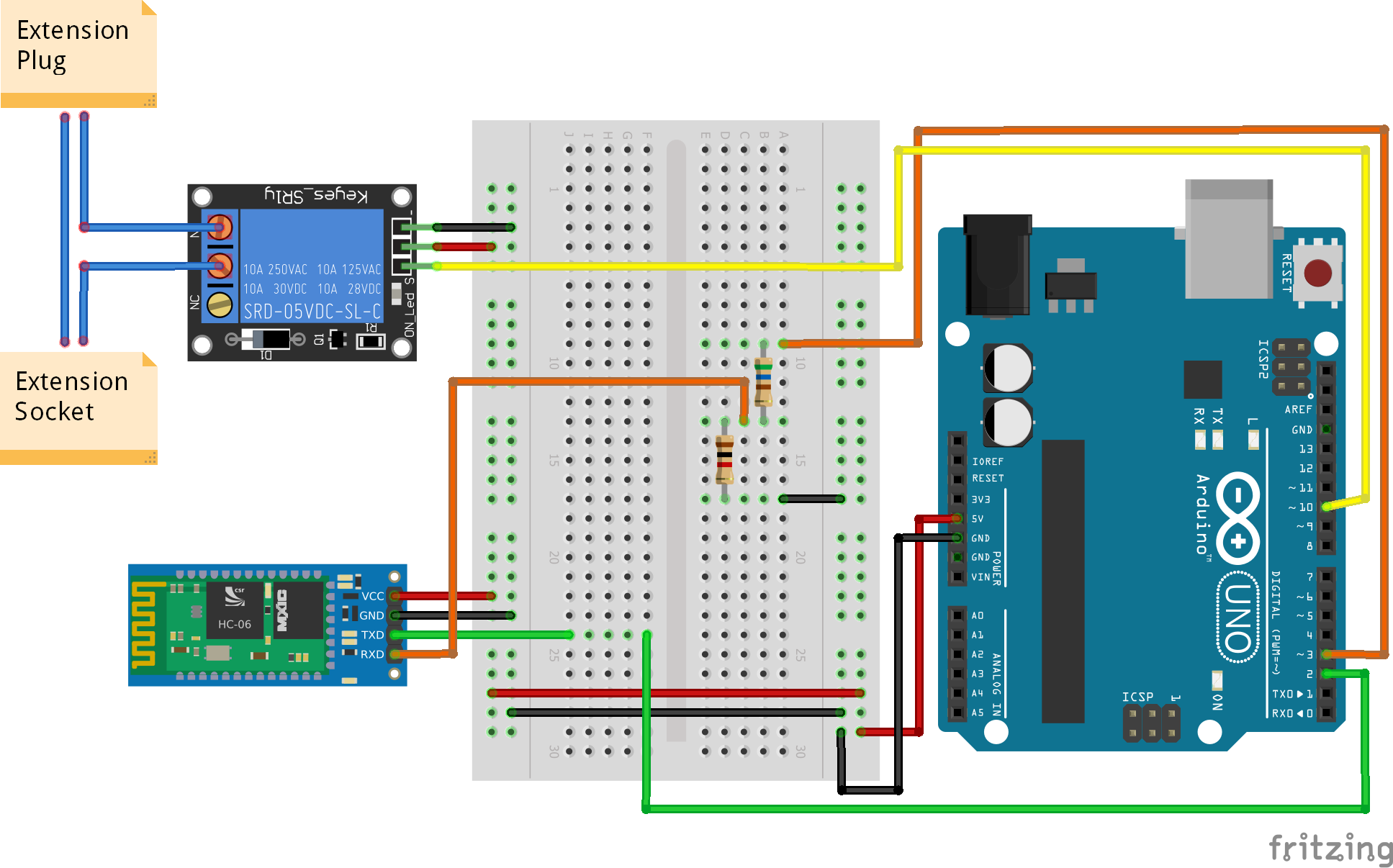
Let's start by setting up our bluetooth module (bottom left component in the figure). As you can see we pull out both 5V and Ground from our Arduino all the way through to the Bluetooth Module (Red and Black wires). For the communication pins we will need to attach the Transmitter pin (TX) to the Arduino's receiver pin (RX) (Green Wire) and the Transmitter pin to the Arduino's Receiver pin (Orange wire). If you check the back of your bluetooth module it will have a label showing how much voltage it's receiver pin can handle (In my case it's 3.3V) and since our Arduino supplies 5V, the bluetooth module would probably burn up after frequent uses, that's why we need to reduce that voltage to 3.3V. Hence, it has been included 2 resistors that work as a "voltage divider" that go through the orange wire. the first R1 resistor is a 560 OHMS while the second one R2 is 1K OHMS. I used these resistors because it was what I had in my equipment but if you have any other resistors maybe you can find the right set for you using this Formula and that brings the voltage down a bit:
Vout = (Vsource x R2)/R1+R2
In my case I got:
Vout = 5 x 1000 / 1560 = 3.2V.. close enough..
(Search for Voltage Divider Calculators on Google and it will give you good explanation and quick calculations).
As for the Relay, we also supply it with both power and ground (Red and Black wires) and a signal wire connected to Arduino's pin number 10 that will command the relay when to power ON or OFF our lamp, for example.
The blue wires represent the wires of the plug/socket extension. Obviously you will not want to connect the relay directly to a lamp's built-in plug extension which you would purposly ruin for this project, so what is recommended is to buy a standalone plug/socket extension. What I did was to buy a smaller wire and add to it both plug and socket just as it's represented in the photo of the slideshow above.
Now that you have your extension, pull out 1 of the wires extension and cut it, you will end up with 2 wire ends (shown in the 2 photos above). But where can you connect these 2 ends to the relay?. The Relay has 3 ports, NC (normally closed), C (Common), NO (normally open). This means that, when the relay is at it's normal state (no signal sent to the relay) there will be a connection between NC and C ports. When a signal is sent a connection will be set between C and NO instead. So that's why we connect our 2 wire ends to both C and NO because we want to send a signal to our relay in order to let the current flow through these two channels and provide energy to our appliance. Great explanation here: http://www.pcbheaven.com/wikipages/How_Relays_Work/
5. Arduino Code#include <SoftwareSerial.h>
#define RELAY 10
#define LIGHT 13
SoftwareSerial btm(2,3); // rx tx
int index = 0;
char data[10];
char c;
boolean flag = false;
void setup() {
pinMode(RELAY,OUTPUT);
pinMode(LIGHT,OUTPUT);
digitalWrite(RELAY,HIGH);
digitalWrite(LIGHT,LOW);
btm.begin(9600);
}
void loop() {
if(btm.available() > 0){
while(btm.available() > 0){
c = btm.read();
delay(10); //Delay required
data[index] = c;
index++;
}
data[index] = '\0';
flag = true;
}
if(flag){
processCommand();
flag = false;
index = 0;
data[0] = '\0';
}
}
void processCommand(){
char command = data[0];
char inst = data[1];
switch(command){
case 'R':
if(inst == 'Y'){
digitalWrite(RELAY,LOW);
btm.println("Relay: ON");
}
else if(inst == 'N'){
digitalWrite(RELAY,HIGH);
btm.println("Relay: OFF");
}
break;
case 'L':
if(inst == 'Y'){
digitalWrite(LIGHT,HIGH);
btm.println("Light: ON");
}
else if(inst == 'N'){
digitalWrite(LIGHT,LOW);
btm.println("Light: OFF");
}
break;
}
}
The Arduino's code shown above is generally structured in 4 phases.
- 5.1. Initializations
- 52. Setup
- 5.3. Loop
- 5.4. Process Command
It is important to note that all the code above is in the Arduino's point of view, meaning that all the 'reading' operations are operations where the arduino is receiving data from some other source, and the write operations are operations where the arduino is sending messages to other source as well. The sequence of usage in our system will be like this:
- a. The user clicks a button in the smartphone engaging a bluetooth command.
- b. The bluetooth module receives it and sends that command to the Arduino.
- c. The Arduino will then process that command and send a signal to the relay to turn it ON or OFF.
- d. The Arduino then sends a sucessfull message to the bluetooth module, where the bluetooth module sends this message back to the smartphone.
5.1.Initializations
In the first few lines of code, we start by including the SoftwareSerial library that will allow us to communicate with the Bluetooth module. It also lets us use different pins as a receiver and transmitter pins than the ones predefined for Arduino (pin 0 = RX and pin 1 = TX). Instead we'll use pin number 2 for Arduino's RX and pin 3 for Arduino's TX. Then we create constants that identifies the pins we wish to use for each of our components, in this case, the Arduino's pin that will controll the RELAY is number 10 and the pin to controll the built-in LIGHT on Arduino's is number 13.(this is optional, if you don't want to use it it's fine). Then, the data structure called 'data' of type 'char' acts as a buffer for our incoming messages from the bluetooth module, and some more auxilliary variables for our data structure ( flag, index, c ) that will be explained in the Loop section.
5.2. Setup
The predefined method 'setup', will be the first method to be executed before our actual intended program starts running. It basically allows us to configurate some of the Arduino's pins and other stuff before the main program executes. Therefore we start by saying that the RELAY pin will be an OUTPUT pin since we want to send a signal to either turn OFF or ON the Relay. The same for the LIGHT pin. Additionally, we can choose if we want to start the program and start sending the signal right away using 'digitalWrite'. In case of the relay we do want to start sending a signal because the way the Relay works is a bit counter-intuitive because the way the relay works is that when a signal is detected by de relay, then it switches itself OFF, else it switches back ON.
5.3. Loop
The loop is the method that, as the name suggests, is iteratively being called in order to repeatedly process whatever information we pass onto it. With that being said, we start by checking if there are incoming messages from the bluetooth module, and if there are, then we enter a cycle to keep reading those messages byte by byte (reading a type 'char' every iteration). About the line of code delay(10), to be honest i'm not completely sure why the code only worked with that delay(10). When I tried without that line of code, the messages weren't being received properly into the array of chars called 'data' (our buffer) and all I got was a bunch of junk in the buffer. My best guess, and it was the reason why I used it, would be the fact that there are different processing speeds in receiving and transmitting of our components, which in this case is the Arduino and Bluetooth Module. In some Arduino code over the web is costume to see some of those delays lines of code and probably some of them are likely to be used for that matter. After this delay, suppose we have read the first byte (char) of our message, we then add it to our buffer and increment the counter called ''index'' to keep adding more bytes iteratively and incrementally along the dimension of the array/buffer. After the message as been read, we exit the while loop and say "yes", there is a message to be processed (by setting the flag to true). And also add a '\0' to indicate the buffer's end. Finnaly, at the end of the loop method we simply check if there are messages to process, and if there is we then call the processCommand method for that matter, clearing/reseting our buffer afterwards by setting the first index of the array([0]) to null ('\0') and setting the counter ('index') to 0. This way our buffer is ready to receive more incoming messages.
5.4. Process Command
Finnally, the processCommand method will be the method that will decide what to do with the bluetooth message received previously in the loop code section. For this project, I decided to send simple commands sent from the smarthphone to the Arduino through bluetooth. To turn the relay ON, a simple message built on the Android application will send the following String as bytes: "RY" (Relay Yes) if we wish to turn the relay ON or "RN" (Relay NO) if we wish to turn the relay off. Like mentioned before, I also included a "add-on" where you can controll the Arduino's built-in LED ( pin number 13 ) and so the commands are "LY" and "LN" but you don't have to use it. Remember that to turn ON the Relay we need to send a LOW signal from the Arduino and vise-versa. The Arduino will also send a status message such as for example "Relay: ON" back to the bluetooth module which in its turn will send to the user.
6. Android CodeIn this section we'll discuss how the Android app was implemented to communicate with the Bluetooth module. I will not cover some aspects of the Android functionality and how you are supposed to do certain things, but mainly the contents of the source code and explain it a bit better. But in general, the app was created using Android Studio (AS), and AS allows you to choose a simple template to start your application, select that basic template. Then, AS has set up all the things you need to start your app, including the Android Manifest which is where you include the app's general properties such as what permissions the app is going to need. A simple blank layout where you can add some components like buttons, and one java source code that initializes the app and controls all the UI stuff on the layout. If you haven't chosen the basic template and chose the empty template instead then you can always create a new activity which sets up a layout and corresponding source file that you'll need. Also the source code and resources can be found on my github: https://github.com/serge144/ArduinoConnectorBT
So here's what we'll cover next:
- Android Manifest
- Simple Layout
- Java Source Code (Ardcon.java + ConnectedThread.java)
6.1 Android Manifest
 <?xml version="1.0" encoding="utf-8"?>
<manifest xmlns:android="http://schemas.android.com/apk/res/android"
 package="flipser.bluetooth">
   <uses-permission android:name="android.permission.BLUETOOTH"/>
   <uses-permission android:name="android.permission.BLUETOOTH_ADMIN"/>
   <application
 android:allowBackup="true"
 android:icon="@mipmap/ic_launcher"
 android:label="@string/app_name"
 android:supportsRtl="true"
 android:theme="@style/AppTheme">
        <activity android:name=".Bluetooth">
            <intent-filter>
                <action android:name="android.intent.action.MAIN" />
               <category android:name="android.intent.category.LAUNCHER" />
            </intent-filter>
        </activity>
    </application>
</manifest>
The android manifest describes the application's main structure and what OS's functionalities will the app make use of. In our case we need to include permissions related to the Bluetooth interface. As we can see from the code shown above, the following lines were inserted in order to use the OS's Bluetooth functionalities:
<uses-permission android:name="android.permission.BLUETOOTH"/>
<uses-permission android:name="android.permission.BLUETOOTH_ADMIN"/>
6.2 Simple Layout
The layout is presented in the following figure:
The Text view is used only to output the messages sent by the Arduino + Bluetooth module. For instance, by sending a message to the arduino, it will send back to the smartphone a response if it was sucessfull, displaying that message in the Text View. Then we have two buttons, the Relay button and Light button to turn on/off the built-in LED found on the Arduino. I believe that it is not necessary to include the code in this case since all you need to do is drag two buttons and a text view somewhere you would like to place it.
6.3 Java Source Code
(Ardcon.java)
The first source file we'll cover is the Ardcon.java file (Arduino Connection). What this file mainly does is to first initialize Bluetooth and make a connection. Then it checks for clicks in our two buttons and do the corresponding operation. So let's start with the initializations:
public final static String MODULE_MAC = "98:D3:34:90:6F:A1";
public final static int REQUEST_ENABLE_BT = 1;
private static final UUID MY_UUID = UUID.fromString("00001101-0000-1000-8000-00805f9b34fb");
BluetoothAdapter bta;                 //bluetooth stuff
BluetoothSocket mmSocket;             //bluetooth stuff
BluetoothDevice mmDevice;             //bluetooth stuff
Button switchLight, switchRelay;      //UI stuff
TextView response;                    //UI stuff
boolean lightflag = false;            //flags to determ. if ON/OFF
boolean relayFlag = true;             //flags to determ. if ON/OFF
ConnectedThread btt = null;           //Our custom thread
public Handler mHandler;              //this receives messages from thread
The Media access control, or MAC address of the bluetooth module is, in my case "98:D3:34:90:6F:A1". In order to find the MAC of your bluetooth module, you first need to turn the circuit ON, or just set some basic circuit just to turn the bluetooth module ON. Then, use your smartphone to check for bluetooth signals, your bluetooth module should come up along with its MAC address. If the MAC address is not shown, try using other devices such as your PC. Then the UUID of the bluetooth module HC-06 is 00001101-0000-1000-8000-00805f9b34fb is always the same, if you are using Android, this number may change iOS is used. (Look up UUID for more information).
Then we initialize the buttons, textviews, flags to determine if the relay and light are turned off or on, a ConnectedThread which basically takes care of sending/receiving messages to/from the Arduino + Bluetooth, and finally a Handler that takes care of processing the messages received from the thread.
@Override
protected void onCreate(Bundle savedInstanceState) {
    super.onCreate(savedInstanceState);
    setContentView(R.layout.activity_ardcon);
    Toolbar toolbar = (Toolbar) findViewById(R.id.toolbar);
    setSupportActionBar(toolbar);
    Log.i("[BLUETOOTH]", "Creating listeners");
    response = (TextView) findViewById(R.id.response);
    switchRelay = (Button) findViewById(R.id.relay);
    switchLight = (Button) findViewById(R.id.switchlight);
    switchLight.setOnClickListener(new View.OnClickListener() {
        @Override
        public void onClick(View v) {
            Log.i("[BLUETOOTH]", "Attempting to send data");
            if (mmSocket.isConnected() && btt != null) {
                if (!lightflag) {
                    String sendtxt = "LY";
                    btt.write(sendtxt.getBytes());
                    lightflag = true;
                } else {
                    String sendtxt = "LN";
                    btt.write(sendtxt.getBytes());
                    lightflag = false;
                }
            } else {
                Toast.makeText(Ardcon.this, "Something went wrong", Toast.LENGTH_LONG).show();
            }
        }
    });
    switchRelay.setOnClickListener(new View.OnClickListener() {
        @Override
        public void onClick(View v) {
            Log.i("[BLUETOOTH]", "Attempting to send data");
            if (mmSocket.isConnected() && btt != null) {
                if(relayFlag){
                    String sendtxt = "RY";
                    btt.write(sendtxt.getBytes());
                    relayFlag = false;
                }else{
                    String sendtxt = "RN";
                    btt.write(sendtxt.getBytes());
                    relayFlag = true;
                }
              //disable the button and wait for 4 seconds to enable it again                switchRelay.setEnabled(false);
                new Thread(new Runnable() {
                    @Override
                    public void run() {
                        try{
                            Thread.sleep(4000);
                        }catch(InterruptedException e){
                            return;
                        }
                        runOnUiThread(new Runnable() {
                            @Override
                            public void run() {
                                switchRelay.setEnabled(true);
                            }
                        });
                    }
                }).start();
            } else {
                Toast.makeText(Ardcon.this, "Something went wrong", Toast.LENGTH_LONG).show();
            }
        }
    });
bta = BluetoothAdapter.getDefaultAdapter();
  //if bluetooth is not enabled then create Intent for user to turn it onif(!bta.isEnabled()){
  Intent enableBTIntent = new Intent(BluetoothAdapter.ACTION_REQUEST_ENABLE);
  startActivityForResult(enableBTIntent, REQUEST_ENABLE_BT);
 }else{
  initiateBluetoothProcess();
 }
}
I'll now give a short overview of the code above.
This is the method that initializes the application and all the UI, we start by getting our references of the buttons and textview from the layout. Then we add some logic to both our buttons. For instance, in the case of the switchLight, the click listener will first determine if there is a bluetooth connection with the module, and if there is, then a message is sent to either turn OFF or turn ON the light. The same applies to the switchRelay button, but in this case we've also included a small timer after an operation is made which disables the relay button for 4 seconds. This is a secure measure since we don't to start messing with the appliance by quickly switing ON/OFF while pressing the button in a rappid manner. Then, with all the button logic completed, we try to make a connection to a bluetooth module right away in initialization. First we check if the bluetooth is ON on the smartphone, if it is not then we must ask the user to turn it off by creating an intent of type BluetoothAdapter.ACTION_REQUEST_ENABLE. This will trigger a dialog window to confirm the bluetooth activation. Then we set a onActivityResult to receive the confirmation of the user like this:
@Override
protected void onActivityResult(int requestCode, int resultCode, Intent data) {
    super.onActivityResult(requestCode, resultCode, data);
    if(resultCode == RESULT_OK && requestCode == REQUEST_ENABLE_BT){
        initiateBluetoothProcess();
    }
}
Then, the initiaBluetoothProcess() method makes the connection to the bluetooth module and creates a handler which is the component that receives information from the ConnectedThread, again, this thread is in charge of receiving/sending bluetooth information to/from the bluetooth module in the arduino. The handler simply updates the TextView with the response text.
public void initiateBluetoothProcess(){
    if(bta.isEnabled()){
        //attempt to connect to bluetooth module        BluetoothSocket tmp = null;
        mmDevice = bta.getRemoteDevice(MODULE_MAC);
        //create socket        try {
            tmp = mmDevice.createRfcommSocketToServiceRecord(MY_UUID);
            mmSocket = tmp;
            mmSocket.connect();
            Log.i("[BLUETOOTH]","Connected to: "+mmDevice.getName());
        }catch(IOException e){
            try{mmSocket.close();}catch(IOException c){return;}
        }
        Log.i("[BLUETOOTH]", "Creating handler");
        mHandler = new Handler(Looper.getMainLooper()){
            @Override
            public void handleMessage(Message msg) {
                //super.handleMessage(msg);                if(msg.what == ConnectedThread.RESPONSE_MESSAGE){
                    String txt = (String)msg.obj;
                    response.append("\n" + txt);
                }
            }
        };
        Log.i("[BLUETOOTH]", "Creating and running Thread");
        btt = new ConnectedThread(mmSocket,mHandler);
        btt.start();
    }
}
(ConnectedThread.java)
As mentioned, the ConnectedThread.java file contains the necessary code to send and receive messages via bluetooth. It also sends informations to the Ardcon.java source file via Handler.
public class ConnectedThread extends Thread{
private final BluetoothSocket mmSocket;
private final InputStream mmInStream;
private final OutputStream mmOutStream;
public static final int RESPONSE_MESSAGE = 10;
Handler uih;
...
First we extend our class with Thread, then we initializa some objects that will allow us to receive and sends messages to the bluetooth module. The Handler is the component that takes care of sending responses back to the UI thread (Ardcon.java) so that we can update the Text View.
public ConnectedThread(BluetoothSocket socket, Handler uih){
    mmSocket = socket;
    InputStream tmpIn = null;
    OutputStream tmpOut = null;
    this.uih = uih;
    Log.i("[THREAD-CT]","Creating thread");
    try{
        tmpIn = socket.getInputStream();
        tmpOut = socket.getOutputStream();
    } catch(IOException e) {
        Log.e("[THREAD-CT]","Error:"+ e.getMessage());
    }
    mmInStream = tmpIn;
    mmOutStream = tmpOut;
    try {
        mmOutStream.flush();
    } catch (IOException e) {
        return;
    }
    Log.i("[THREAD-CT]","IO's obtained");
}
So our ConnectedThread receives a connection to the bluetooth module called BluetoothSocket and the Handler. This constructor initializes the Input and Output streams of the communication.
public void run(){
    BufferedReader br;
    br = new BufferedReader(new InputStreamReader(mmInStream));
    while(true){
        try{            String resp = br.readLine();
            Message msg = new Message();
            msg.what = RESPONSE_MESSAGE;
            msg.obj = resp;
            uih.sendMessage(msg);
        }catch(IOException e){
            break;
        }
    }
    Log.i("[THREAD-CT]","While loop ended");
}
Then, we overwride the run method extended from Thread, in this method, there is a loop that is contantly looking for new messages that have arrived, and if so, then it sands back to the UI thread via handler.
public void write(byte[] bytes){
    try{
        Log.i("[THREAD-CT]", "Writting bytes");
        mmOutStream.write(bytes);
    }catch(IOException e){}
}
public void cancel(){
    try{
        mmSocket.close();
    }catch(IOException e){}
}
Finnally, these two methods are in charge of writting (sending bytes) through the Outputstream to the Bluetooth module and to cancel the connection.


Comments
Please log in or sign up to comment.