James Lewis
Published © MIT

Capacitive Coin Bank

Coin bank activated by capacitive touch.

IntermediateFull instructions provided4 hours779
Capacitive Coin Bank

Things used in this project

Hardware components

MSP430 Microcontroller
Texas Instruments MSP430 Microcontroller
MSP430FR2633. MSP430 with an integrated capacitive touch controller called CAPTIVATE.
×1
Pyramiduino
It's just a triangle shaped Arduino Nano.
×1
Adafruit PowerBoost 1000 Charger
×1
Adafruit Lithium Ion Polymer Battery - 3.7v 500mAh
×1
Perma-Proto Breadboard Half Size
×1
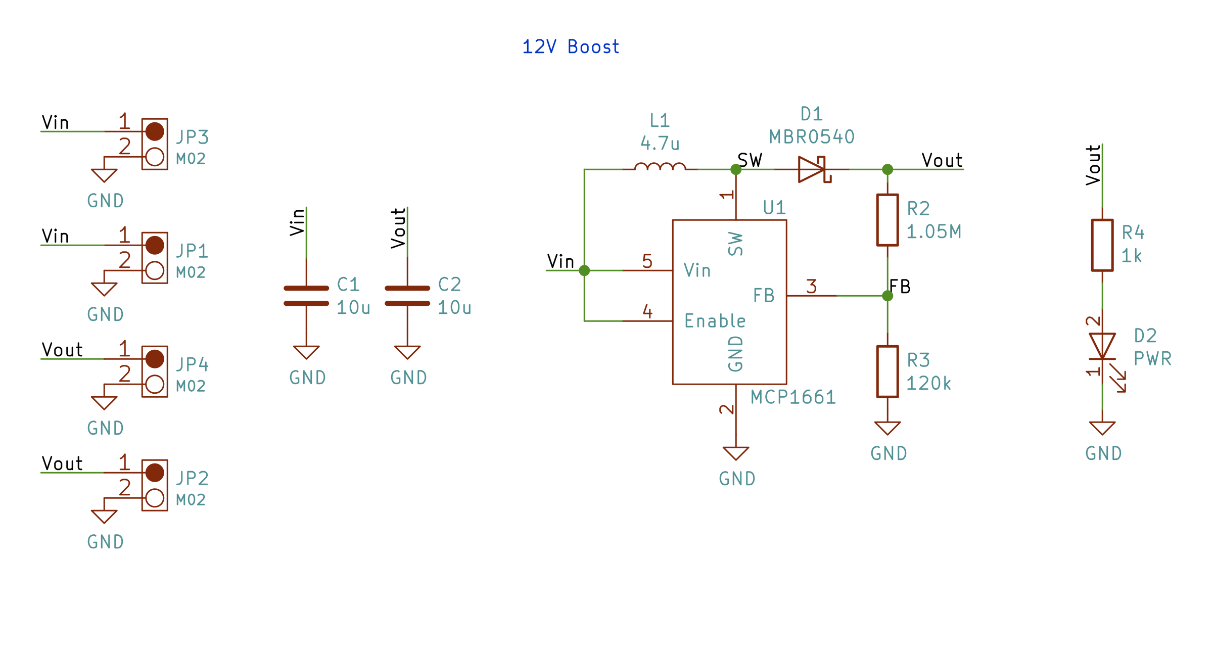
5v to 12v Boost Converter
MCP1661 based converter, design files included.
×1
Adafruit Coin Acceptor - Programmable 4 Coin Type
×1
Generic OLED 2.7" Display
×1
6mm Copper Foil Tape (From 3M)
You only new a few centimeters, but a role of this tape is only $12. You can make all the capacitive touch buttons you can think of!
×1

Software apps and online services

Arduino IDE
Arduino IDE

Hand tools and fabrication machines

Laser cutter (generic)
3D Printer (generic)
Hot glue gun (generic)
Cyanoacrylate (Super Glue)

Story

Read more

Custom parts and enclosures

MSP430 Shelf

Glue this to the top slot
File missing, please reupload.

Shelf for all other electronics

Tape the battery to the shelf and glue it into place.

Fusion 360 Project

The final enclosure with all of the panels assembled together.

Main Case - Laser Cutter

Files to laser cut to make the main case.

Drawer - Laser Cutter

Cut and glue these together to form the drawer

Rails - Laser cutter

These rails get glued to the drawer. Use 3mm acrylic.

Slides for drawer

These glue to the main case's bottom piece. Print 2 of them.

Side Slides for drawer

These clue to the side pieces of the main case. Print 2 of them.

Handle for Drawer

You know, for grabby grabby actions.

Error uploading file to Sketchfab.

Schematics

12V Boost Schematic (Image)

Schematic for the 12V booster. This drives the coin acceptor. The circuit is suitable for 50mA continuous and up to 500 mA peak. See repository link under code for the KiCad 5 design files.

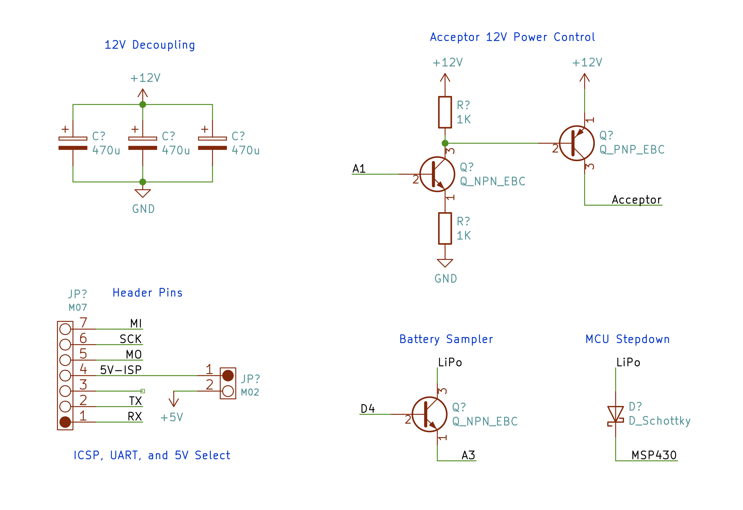
Breadboard Circuits

Some small "glue circuits" that I soldered to an Adafruit perma board. See the code repository above for the KiCad 5 design file. (Only schematic)

Code

Code

The code directory contains code for both the MSP430 and the Arduino.

Credits

James Lewis

James Lewis

11 projects • 644 followers
Electronics enthusiast, Bald Engineer, and freelance content creator. AddOhms on YouTube. KN6FGY.

Comments