


Hardware components | ||||||
| × | 1 | ||||
| × | 1 | ||||
| × | 1 | ||||
| × | 1 | ||||
| × | 5 | ||||
| × | 1 | ||||
Software apps and online services | ||||||
 |
| |||||
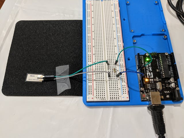
The vibration sensor is a piezo film attached to a pair of leads with riveted lugs. There is a transparent polymer protective coating over the entire body to inhibit atmospheric oxidation of the surface of the film. The low cost of this sensor makes it very popular for simple applications where impact (e.g. patting a toy) translates to switch operation.
Upon receiving a nominal force (i.e. strain), the sensor generates a differential voltage. The capacitance of the sensor is:
· Proportional to the surface area
· Inversely proportional to the applied force
Applications Some of the basic applications for this sensor are:
· Impact event capture:
o Time
o Frequency
· Tap switch
· Vibration sensor
· Shock detector (product damage)
· Alarm system
· Other transducers:
o Distance sensor
o Acceleration sensor
o Flow rate measurement
o Parking aids
o Level sensors
o Ultrasonic air transducers
o Sound pick-ups
Specifications Range Description
Signal 0 – 70 VDC Analog
Sensitivity 50 mV/g
Operating Temperature 0 – 70 °C
Operation
The imposition of mass on the sensor decreases its sensitivity and resonant frequency. The displacement or bending of the sensor’s surface generates a high strain by the piezo element resulting in a detectable voltage. The voltage may be read in two modes of operation:
· Analog
· Digital
AnalogIn the analog mode, the designated analog pin for the vibration sensor is read continuously. Action is taken if the reading traverses a threshold. The higher the value the greater the stress on the sensor. Of course, it is prudent to insert a nominal delay in reading the data so that other tasks (e.g. transferring data to the serial port) may be granted a share of the processing time by the micro-controller.
DigitalIn the analog mode, the designated digital pin is monitored for a pulse. A direct reading of the pulse will permit action to be taken. A more efficient way is to let the pulse signal trigger a call to a service routine. The Arduino terminology for this routine is Interrupt Service Routine (ISR).
PulseThe following state changes in the pulse of assigned digital pin can be leverage to trigger the interrupt:
State Value description
LOW Value is low
CHANGE Value changes (any)
RISING Value changes from low to high
FALLING Value changes from high to low
Interrupt Service RoutineThe common name for this routine is interrupt handler. The advantage of this method is that the microcontroller is no longer bound in a continuous loop examining the sensor state directly. When the desired pulse condition is detected by the microcontroller control is transferred to the ISR where time and resource sensitivity requires the processing to be as short as practical. In the simplest example, it is a matter of simply setting a flag.
The main loop examines the flag and branches accordingly. The main loop could be in a computationally intensive section of the code but it would be interrupt to delegate processing by the ISR.
There are some limitations for the UNO R3 board with respect to the availability of interrupts on the UNO R3 board as shown below.
Interrupt number Digital pin number
Arduino UNO R3 INT.0 2
INT.1 3
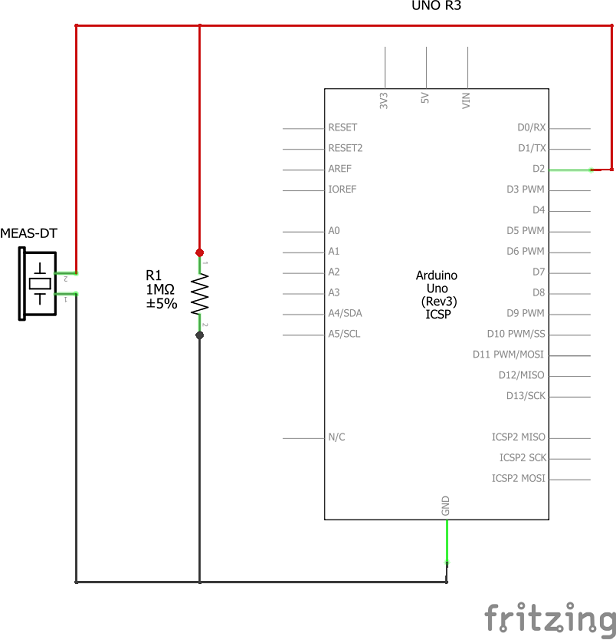
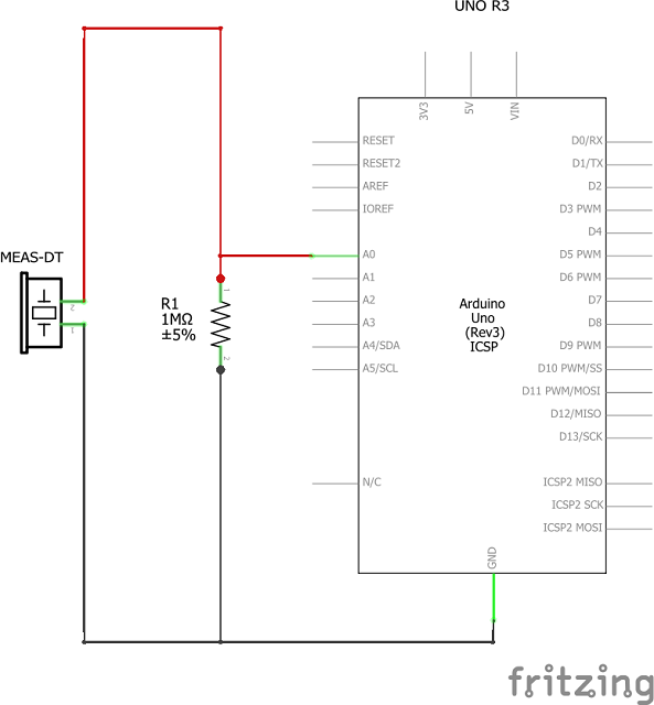
Schematic
A schematic diagram applicable for simple tests with the sensor is shown below for measurement of the voltage pulse from the sensor element on a digital pin is shown below for the analog and digital test cases.
The 1 MΩ resistor, derived from manufacturer’s datasheet, ensures that the voltage surge from flexing the sensor is managed appropriately.
Analog
Digital
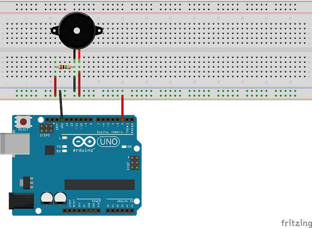
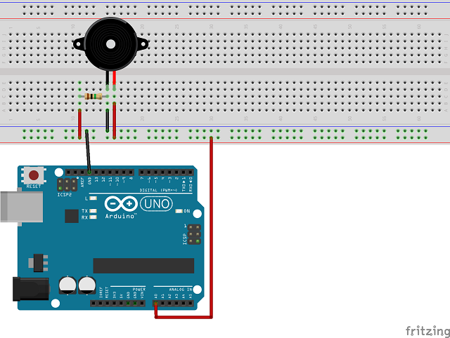
The assembly diagrams below for the analog and digital examples require two considerations:
· There was no readily available shape for the MEAS-DT vibration sensor in the Fritizing libraries. the piezo speaker shape was used as an equivalent. Please view the picture of the vibration sensor in a preceding section.
· The common bus for the GND and VDC rails on the breadboard were leveraged for the limited purpose of this note. In practice, it would be more appropriate to refrain from using the VDC rail for this purpose.
Analog
Digital
The simple screen shots below for the analog and digital test cases are essentially to demonstrate that the solution works. The focus in this note is on detection. What to do after the detection is subject to your interests. The actions with the data in a practical solution, of course, will be vastly different but are beyond the scope of this article.
AnalogWhen the sensor is at rest, the output voltage is close to zero. The noise may be attributable to secondary movement of the sensor owing to imperfections in keeping the entire assembly at rest. Flexing the sensor lead to the spikes shown in the plot. The greater the flexing, the higher the value read from the analog pin. This precisely why the resistor (or a Zener diode) is mandatory even for the simplest tests.
The digital output is for the limited case of RISING pulse only – sensor is in the LOW state and it receives an impact (or flexed) that sends the pulse to the HIGH state.
This introductory note examined the application of a low-cost vibration sensor with Arduino UNO R3 board operating into basic modes:
· Analog
· Digital
The customization of the action(s) was left to the discretion of the developer who will embark on the test exercises. The potential for the application of this sensor to common home automation scenarios was summarized in the introductory sections of the note.
DT Series Elements with Lead Attachment


Comments
Please log in or sign up to comment.