


Hardware components | ||||||
| × | 1 | ||||
 |
| × | 1 | |||
| × | 1 | ||||
| × | 1 | ||||
| × | 1 | ||||
Software apps and online services | ||||||
 |
| |||||
The three basic types of hobby motors used with single-board computers are:
- Direct Current (DC)
- Servo
- Stepper
This note is limited to a simple (and single) servo motor. There is an accompanying video presentation. The use of a stepper motor will be illustrated in a future article.
Servo MotorServo is a truncation of the term, servomechanism, that describes the operation of the integrated solution to move a shaft to a desired position. The movement can be rotational for an angular position (as illustrated in this note) or can be linear too. The servo motor permits a degree of control over the angle of its shaft using the following functions:
- Motor
- Electronic controller with integrated potentiometer
- Gear train
- Drive shaft
The rotation angle can be converted to a linear position with additional mechanical gear components. The angle of the shaft (from a reference position) is fed back to a closed-loop servomechanism (i.e. electronic controller) for comparison with the desired position that is sent as a signal to the solution. Unfortunately, for low cost solutions, it is impractical for the actual angle of the shaft to be returned as an output signal.For industrial applications, the speed of the motor can be a control variable too.
The motor can be driven by AC or DC. The latter is the preferred choice for small and hobby applications. It is important to understand that the motor component of the servo system is constantly running. The output shaft however stays at the set position.
Pulse Width ModulationThe most elementary way to control the angle of the external shaft in a servo motor uses the technique, known as Pulse Width Modulation(PWM), as shown below:
Figure 1: Using pulse width modulation to set shaft angle
While a servo motor has a limited angle of rotation (i.e. 180 degrees), full rotation servo motors are gaining in popularity. The shaft position for these servo motors extends to full 360 degrees. The position is attained through clockwise or counter-clockwise rotations as appropriate.
The pins on the Arduino board that support PWM have the tilde character, “~”, as a prefix. The pins are 3, 5, 6, 9, 10, and 11.The method, analogWrite, is available to write to the pin as follows:
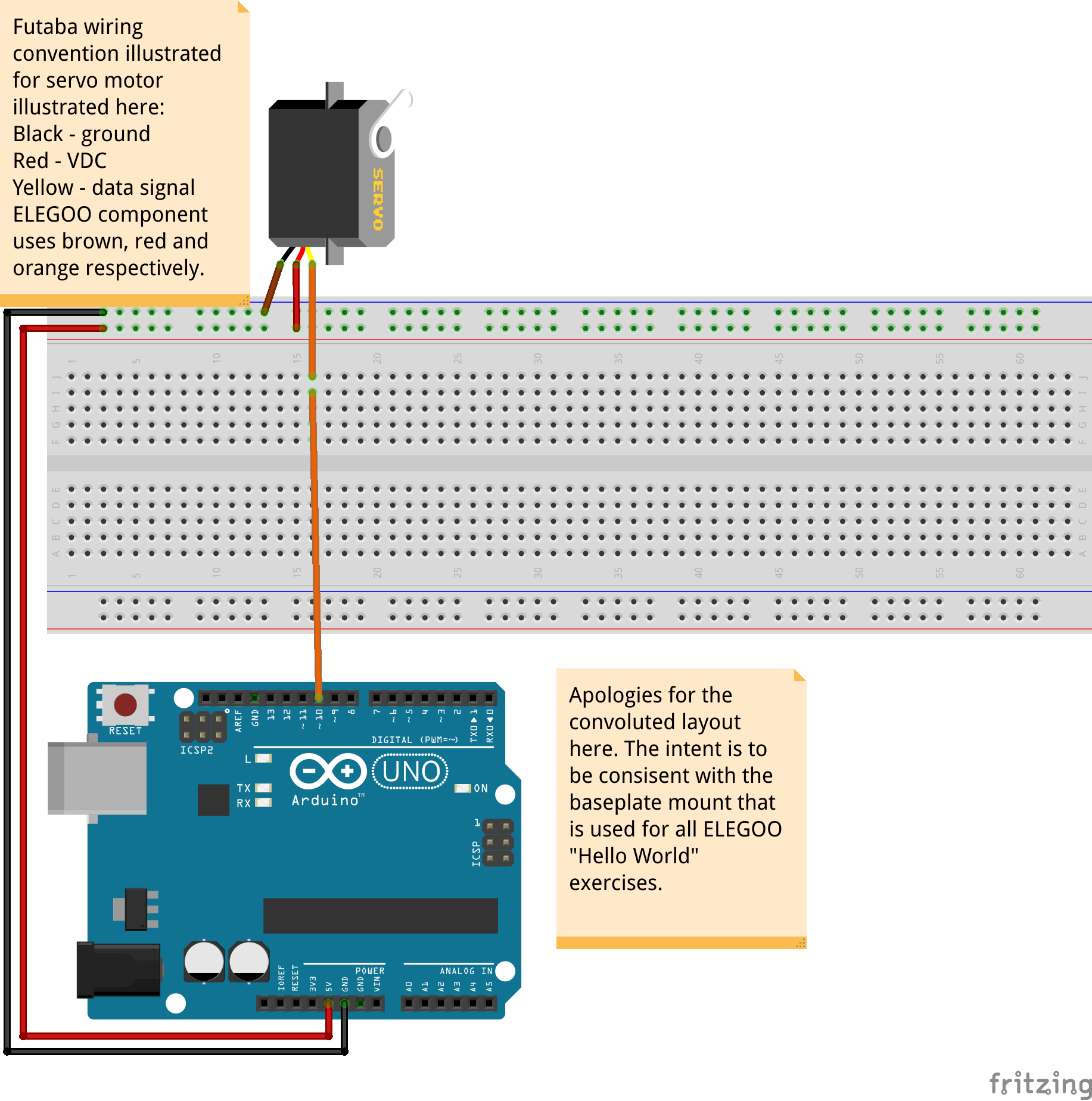
Controlling the MotorThe Arduino UNO R3 board has the following limitations for the flow of current:
- Under USB power: 500 mA (protected by polyfuse but bypasses onboard 5 V voltage regulators)
- Under external power (barrel connector): 500 mA – 1 A
If both connections are used then the power from the barrel connector is preferred as long as the voltage is above 6.6 V DC.
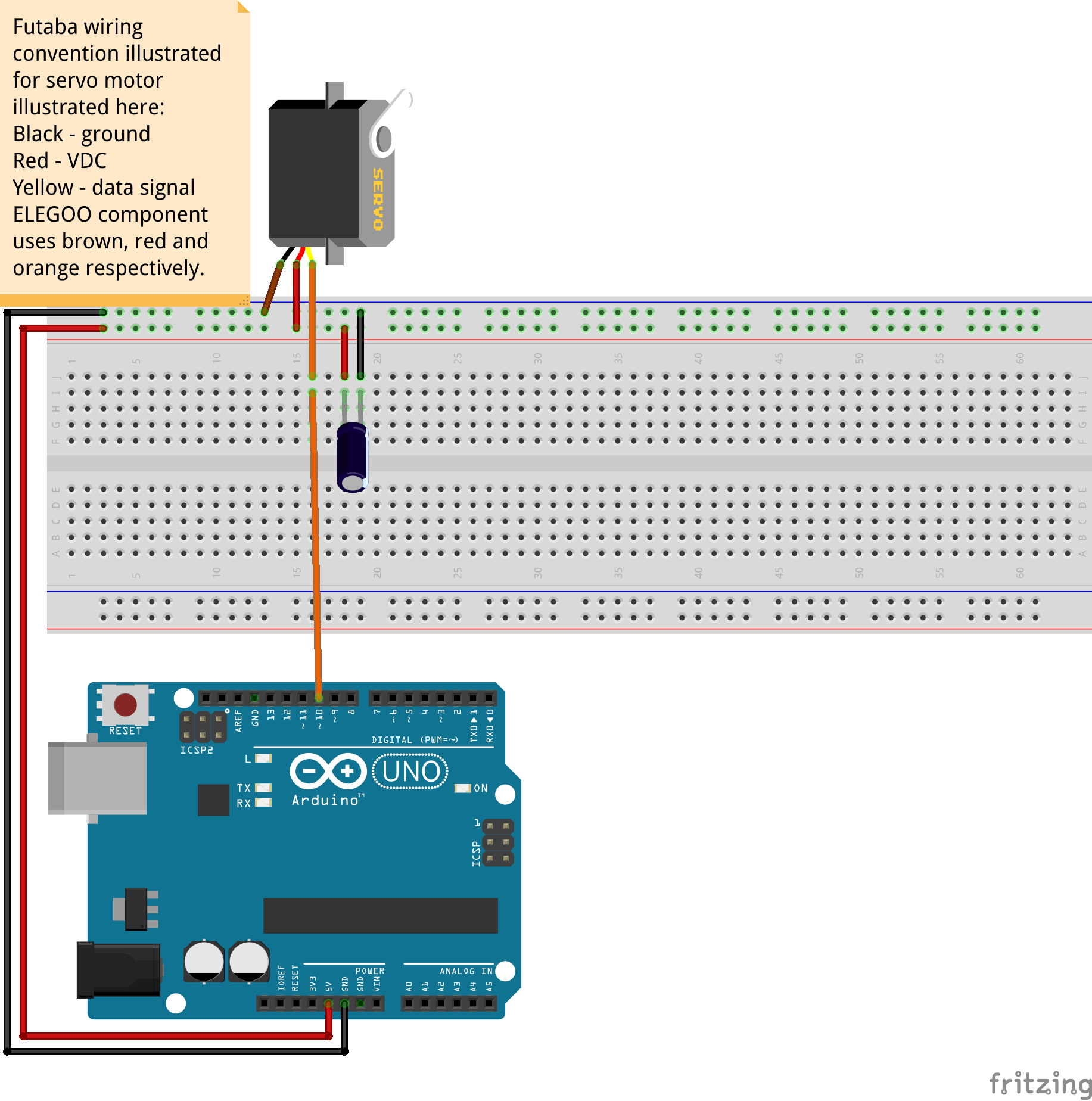
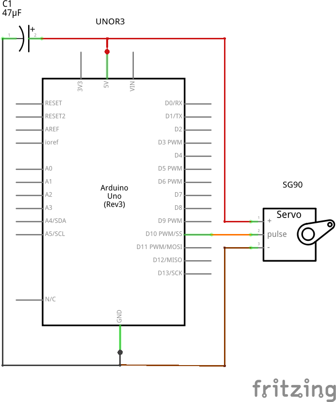
Since the servo motor may place a current surge for the power, a simple electrolytic capacitor, nominally rated at 470 µF, can smooth the distribution as shown below in the second schematic diagram.
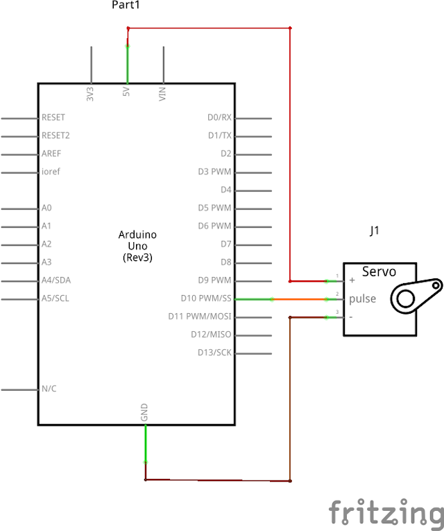
A more robust solution uses a separate power supply for the motor as shown in the schematic diagram below where a common ground connection is required.
SG90 Servo MotorThe most popular servo motor for hobby applications is the TowerPro SG90 model that is available in analog and digital versions. This note is limited to the demonstration of the analog model.
“There are many counterfeit versions of TowerPro servo motors from dealers in China that are being sold on eBay, Amazon, Alibaba and other similar websites. If these dealers removed the TowerPro logo from the corresponding photos and product descriptions, they are selling counterfeit low quality servo motors.Please ensure that the supplier is an authorized licensee selling genuine products before you purchase the corresponding goods. Your cooperation in preserving intellectual property rights of original owners will help us continue to provide superior and strategic solutions for you.” - TowerPro
Sadly, wanton disregard for intellectual property ownership occurs universally – no need to single out companies in Schenzen for this particular product. Obviously, the sentiment “one gets what one pays for” prevails for these types of products. For example, some of the counterfeit versions do not operate over the full rotational range design angle (i.e. 180 degrees). Others are not consistent in their rotation owing to lower stall torque limitations.
Test CasesThe rotation of the servo motor relying on the standard Arduino Servo library performs the same operations in two ways:
- The application specifies the angular position in degrees
- The application specifies the pulse width that the servo uses to establish the angular positions
The following code snippet illustrates the iteration from 0 to 180degrees for the rotational position:
for (int i=0; i<=180; i+=1) // iterate through all positions from 0 to 180
                            // degrees
{
    myServo.write(i);    // set the shaft angle to corresponding orientation
    delay(100);          // 100 milliseconds hold for test use only
}
The following code snippet illustrates the iteration from minimum to maximum pulse width (which in turn represents the available angle of rotation for the servo motor):
for (int i=pwMin; i<=pwMax; i+=1) // iterate through all pulse width values
                                   // from pwMin to pwMax
{
    myServo.writeMicroseconds(i);// set pulse width for desired angle and
                                // rotate shaft to corresponding position
    delay(5);                    // 100 milliseconds hold for test use only
}


Comments
Please log in or sign up to comment.