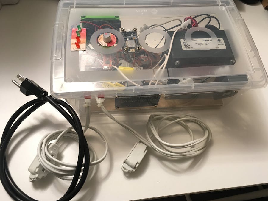
There are tons of battery banks on the market, but for anyone looking for a mobile outlet, options are limited. The multitude of 120V AC banks we could find were limited by combinations of price, portability and performance. Now this is where our project, PowerON, comes in! Out of the box, it can convert 17 to 30V DC to 120V AC, with the capability of automatically switching to an outlet when one is detected. The user is able to control the box through a magnetic rotation knob or on the online dashboard.
Most of all, this project offers a smooth sine waveform thanks to Infineon's CoolMOS Superjunction transistors. The smooth current waveforms created work well with a wide variety of household equipment. Inductive loads and TRIAC-based dimmers in particular are especially sensitive to square wave voltages, with fluorescent lamp ballasts buzzing, motors heating up, and dimmers showing unexpected behavior. Thus, a waveform closely resembling the sine wave supplied by utility power would be more compatible with various appliances.
How it worksThe waveform is generated using an Arduino Uno running code for sinusoidal PWM, also known as sPWM. This produces two PWM sine half waves, which are used to drive the halves of the step-up transformer via the MOSFETs. The capacitor and inductor on the primary side filters out the high-frequency switching noise, resulting in a relatively sinusoidal waveform at the output of the transformer. Then, the current is filtered by two capacitors, which improves the waveform stability over a range of different loads.
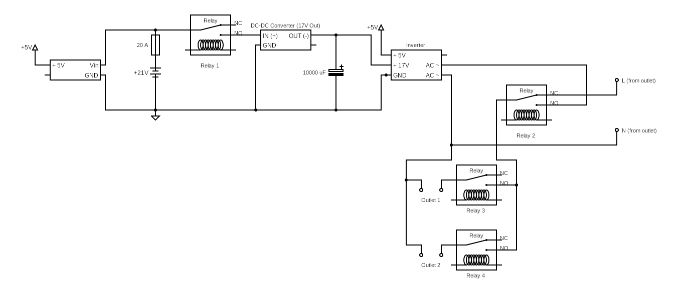
The mains power coming out of the inverter now goes into a 4 channel relay board, which acts as a transfer switch to select between mains power and inverter power, as well as which output(s) get it. This relay board is controlled by a NodeMCU with Infineon's XMC Magnet2GO acting as a contactless control switch. Using it, the user can select between using backup power (from inverter), mains power or an auto switch mode which uses the backup in case the mains goes out.
1. Generate a sinusoidal waveformWe began by brainstorming different ways to generate an AC sine wave from DC. Motor-generators were the original way, but they have many issues including frequency/voltage stability and mechanical parts wearing out. The next way would be using pulse-width-modulation to produce an analog waveform, which would be a sine wave. This results in an extremely stable frequency, and relatively stable voltage. With an abundance of open-source microcontrollers available today, it would be easy to do just that. Thus, we settled on this idea and went ahead.
Code for sinusoidal PWM, also known as sPWM, was obtained from Github, by user Terbytes (here) and run on an Arduino Uno. The next part of the challenge was driving the step-up transformer and smoothing the waveform. PWM, by nature, involves plenty of steps and leads to excessive noise if not properly handled. Since the Uno could only supply 5V at a limited current, we used the Infineon's CoolMOS Superjunction MOSFETs for fast, high current, reliable switching performance.
Afterwards, it was a matter of trial and error to find the optimal values of filtering to achieve a reasonably sinusoidal waveform. This was repeatedly checked using an oscilloscope, in addition to a variety of inductive loads which are highly sensitive to poor waveforms. In the end, we discovered that 6.2uf on the output, along with 15uf on the input and a small custom wound inductor worked best. (inductor value in schematic below is approximate, use 16 turns of 18AWG enamelled wire on a ferrite core)
Unfortunately, we soon realized that the noise coming from the transformer would occasionally cause the Arduino to reset and shut down. To combat this, Zener diodes were added between the pin (9/10) and ground to absorb any stray voltages which may cause problems. This improved the reliability of the inverter, especially when operating fans (inductive loads).
Now, it was on to installing the parts into the box together. It was extremely important that we planned out all the components and their exact regions to avoid unnecessary crossing over and long wires.
The Arduino Uno's pin 9 and 10 were connected to the gates of the MOSFETs directly. In addition, gate bleeder resistors were added to prevent static damage, and Zener diodes added to block high frequency feedback from interfering with the Arduino and causing it to shut down.
DC input was provided by a battery, which is usually 24V as two 12V lead acid batteries connected in series. This power then goes into a DC-DC converter to reduce the voltage to a precise 17.3V in order to produce 120Vrms at the output of the inverter. (Calculation: (17.3*10)/sqrt(2) = 122V, including losses drops to 120V) A separate 5V power supply was produced using a second DC-DC converter, which operated the Arduino as well as the NodeMCU. Main 17.3V power would be used to drive the transformer via the MOSFETs in a push-pull configuration, meaning the two halves of the center tapped primary winding would be powered alternatively, generating an alternating magnetic field and ultimately and alternating current at the high voltage secondary output.
Capacitive and inductive filtering was used to smooth out the waveform to make it look sinusoidal, and without them, there would be an extreme amount of noise in the output, barely appearing sinusoidal. As a result of being amateurs, all values for the capacitors and inductors were obtained through trial and error testing to find the combination which gave the best waveform when viewed on an oscilloscope.
Lastly, the AC exiting the transformer was switched through the relay board for output control.
3a. Magnet sensor readings and relay controlWith the power hardware laid out, we can now enable the functionality to toggle our two outputs and set the power mode of the whole contraption. We first implemented basic hands-on control through the use of Infineon's 3D TLE5012B GMR sensor. This sensor, which is also mounted on an Infineon Sensor 2Go board, can be paired with a magnetic knob to allow the user to control settings by turning the knob to an angle and pressing down. We went with this method of control because we felt that it allowed for the most intuitive, responsive and low-profile method of tactile control.
Note: Though the evaluation board is quite useful, it is not required for this project. You can snap off the sensor or get the IC by itself, if it's more convenient for you. We kept the board as it was easier to mount the knob to the sensor.
The board that will be responsible for relay control and communication with the magnet sensor will be a NodeMcu ESP8266. Any ESP8266 should do, but the NodeMcu board is known to be quite stable. Also, it has quite a few IO pins, which will be helpful. This tutorial will cover implementations with the NodeMcu board, but you can rename your pins to suit your board. Just make sure to have one analog pin and 4 digital pins available. The benefit of an ESP board is that it has WiFi connectivity, and runs on 3.3V logic, which is what our magnet sensor runs on as well.
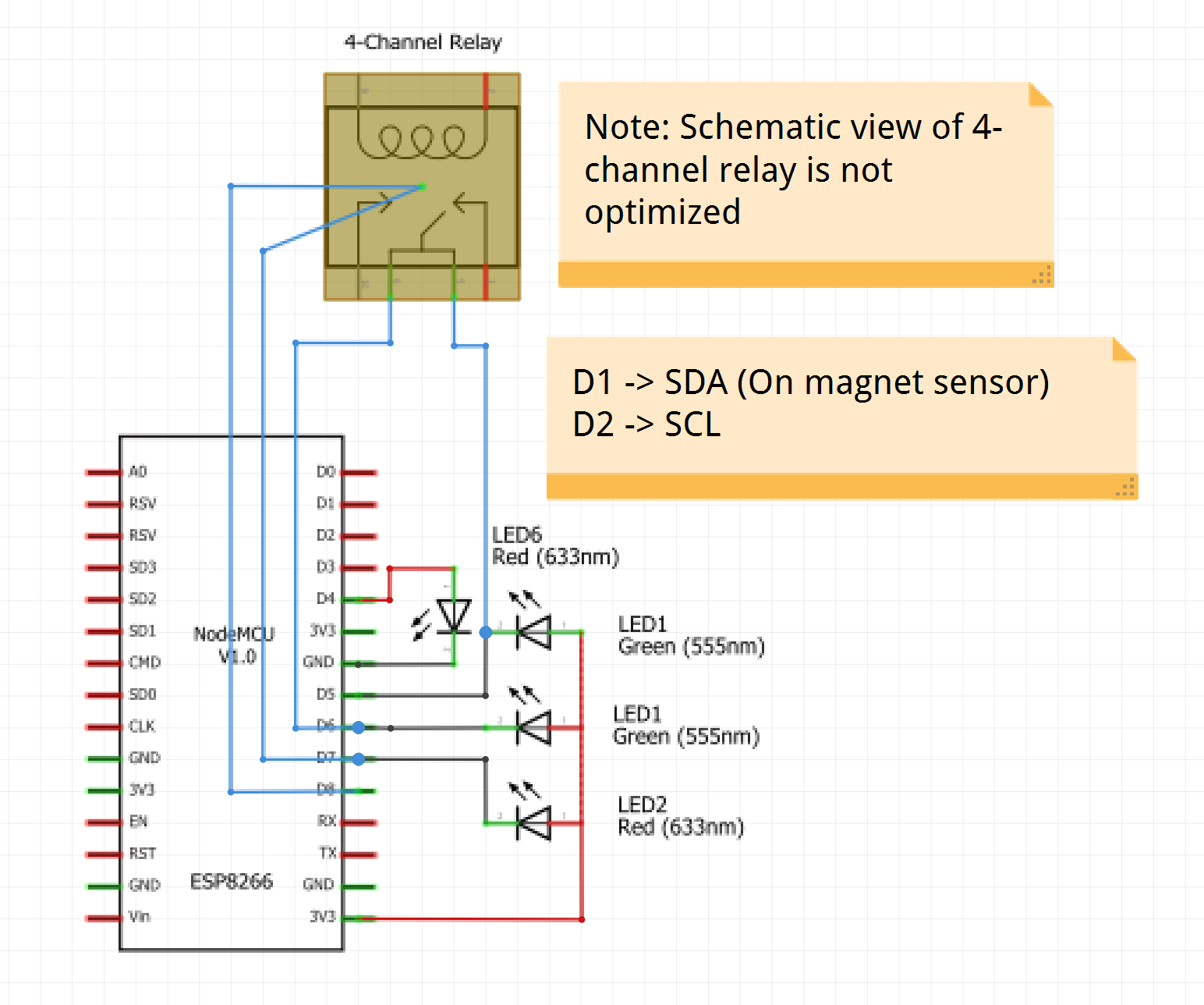
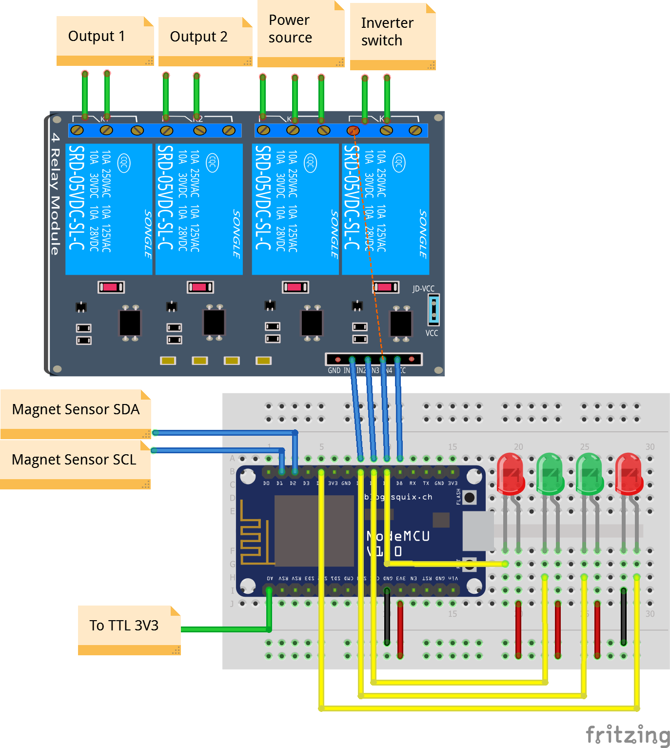
To communicate with the chip, we used I2C. Simply connect the SCA, SCL, 3v3, and GND pins of the sensor to the respective pin names on the ESP8266. Then, open up the Arduino IDE. Install and select the ESP8266 board if you haven't yet, and install Infineon's library for its magnet sensor here. If you aren't familiar with the process, simply download the repository as a.zip file, then open up the Arduino IDE. You can install the library by navigating to Include Library > Add.ZIP Library... and selecting the.zip file you just downloaded. Use this process for the other libraries we'll install.
Now, connect the ESP8266's pins to that of the 4-channel relay module: D5 -> In1, D6 -> In2, D7 -> In3, D8 -> In4. Since we want to enable an automatic power mode, we need to detect if the line in from the outlet in order to switch between the battery and outlet. To do this, connect the analog pin of the ESP (A0) to the 3.3v output of the USB to TTL converter plugged in to the outlet.
Finally, to display the status of the switches and power sources, we used 4 LEDs; used for the socket 1 indicator, socket 2 indicator, battery mode indicator and outlet mode indicator. The anode (long end) for the first 3 LEDs are connected in parallel to the control pins of the In2, In3 and In4 relay control pins. The anode for the last LED is connected to D4 on the ESP8266. The cathodes of all the LEDs are connected to GND on the ESP. If you need more help with the wiring, feel free to check out the schematics and diagrams below. Also, the corresponding pins are set in the knob.ino file.
To keep track of the controls and displays, we've created labels to use in Adobe Illustrator. They are included below, and in our Github repository.
3b. Connecting to the internetWith in-person control set up, we can proceed to control via an online dashboard. The general process is as follows:
- User controls the output states and input power source via the magnet knob, which the ESP8266 interprets
- ESP8266 controls the device's outputs via a set of relays
- ESP8266 posts the status of the relays to a Node.JS server via socket.io.
- The server, upon receivin
gthe request, posts the new data to all clients connected to it - This data will be received by the ESP8266 as well as any clients on the web
- Clients may also post data to the server via socket.io if any changes are made online
First, install this socket.io library and the arudino json library. The socket.io library enables the ESP module to connect to our server, and the Arduino JSON library allows us to parse JavaScript JSON variables and create our own JSON variables to send back to the server.
If you haven't yet cloned our GitHub repository, do it like so on your git bash:
git clone https://github.com/JonathanXu1/SuperjunctiON
Navigate to SuperjunctiON/knob/knob.ino. That's the Arduino file for the ESP8266. Open it, and scroll to lines 24-28:
// Networking variables
const char* ssid = "SSID";
const char* password = "password";
const boolean localMode = false; //Change to true if using localhost
String host = "superjunction.herokuapp.com"; //Replace with your ip if on localhost
Replace ssid with your WiFi name, and password with your WiFi password. We won't worry about the rest for now. Now upload the code to your board, and you should be able to log in to your local WiFi. If you're curious, here's the WiFi connection code, which is on lines 101 -113.
while (WiFi.status() != WL_CONNECTED && i++ < 20){
   delay(500);
   Serial.print(".");
 }
 if(i == 21){
   Serial.println("");
   Serial.println("WiFi failed to connect");
 } else {
   Serial.println("");
   Serial.println("WiFi connected");
   Serial.println("IP address: ");
   Serial.println(WiFi.localIP());
 }
From this, you should be able to connect to your local WiFi. Verify this by opening your serial monitor to a baudrate of 115200.
Stash and commit your changes in git bash:
git add .
git commit -am "make it better"
With the ESP8266 up an connected to WiFi, we need to set up a server for it to communicate to. There are a number of options available for IoT projects such as these, but we decided to use a Node.JS application hosted on Heroku. Though it is more complicated than beginner-friendly apps such as Blynk or aREST, Node.JS is compatible with multitudes of powerful libraries and APIs, and allows full customization in terms of communication with the client. Speaking of which, if we built the entire backend and frontend from scratch, we'll be able to control and customize the UI to our own liking. Furthermore, popular and open-source platforms such as these do not limit the creator through paywalls and set-in-stone UI components.
Heroku's pay-as-a-service offerings are more than enough for us in its free tier. It's fast, easy to use, and allows for an extremely streamlined experience for hosting projects for the first time. It even works seamlessly with git repositories, which is perfect for projects of all sizes. In fact, we're going to set up a Heroku remote off our main repository because of that. If you're a little confused about what git is, you can check out this introduction. Codeacademy has a nice interactive tutorial to get familiar with git.
Start by creating a Heroku account. Then, on your Heroku dashboard, hit New, then click Create new app.
Next, install the Heroku CLI from here. Then, open your git bash in the directory of your recently cloned repository, and run the code below in your git bash, replacing project with your project name. For example, my first line would be
git remote add heroku git@heroku.com:superjunction.git
git remote add heroku git@heroku.com:project.git
Now, you can push the code from our repository to your personal Heroku remote. Essentially this is how you upload your code to the Heroku server. You may be prompted to log in on your first use of the Heroku CLI.
git push heroku master
You'll now see this message if your push has been successful:
Now ensure that at least one instance of the app is running:
heroku ps:scale web=1
If you're curious about the inner workings of the Node.Js code running on your Heroku server, you can check out the server code on index.js. Essentially, the server listens for specific messages on socketio. For example, when a client sends it an updateData command, the server pings all the clients about the current states of the relays.
Now that a server is up and able to communicate with any clients connected to it, we need a front-end UI to control and view the status of our box. Currently, only the ESP8266 has the functionality to act as a client. To code the frontend, it's a simple matter of HTML. You can see what we did on index.html.
We used the MaterializeCSS library to easily create aesthetic and modular web components. So we've made switches and radio button groups. Now with the use of JQuery, we detect if there's a state change when the user toggles any of these elements. If so, we get the value of the elements and send the updated data to the Node.js server through the updateData method in socket.io. Also, if there is any incoming updates from the server, the respective front-end elements are updated. Now you can control the project both in-person and online!
The example shown above is hosted on our own Heroku application. To view your project on Heroku servers, you can run the following to see it on the url provided by the CLI:
git push heroku master
Alternatively, you can run your project on localhost. The only downside is that you won't be able to connect to your locally hosted page outside your localhost network.
heroku local web
To view your locally hosted page, enter localhost:5000 as the URL in your browser.
Now, you can go on to connecting your ESP8266 to your server. Go back to knob/knob.ino. On line 27-28 you can see the following.
const boolean localMode = false; //Change to true if using localhost
String host = "superjunction.herokuapp.com"; //Replace with your ip if on localhost
If you've hosted your code on Heroku:
- Replace the host String with your heroku page's URL
If you're hosting locally:
- Change the localMode boolean to true
- Replace the host String to
localhost:5000
The code has also accounted for offline operation of the box, so if the ESP cannot connect to either the WiFi or the server, it will simply run without being able to send/receive data online.
6a. Installing the hardwareTo install the hardware for this project, you will need a soldering iron, screwdriver, glue gun, and cordless drill with drill bits ranging in size from 1/8'' to 1/2''. The exact placement of the components will vary depending on the enclosure of your choice. For us, we decided to install the main devices towards the sides of the box, leaving space in the middle to run wires as needed.
Using the drill, drill holes for all power cords, mounting holes for the boards, indicator LED's and switches. Secure the devices using appropriate mounting implements, such as screws/nuts for the boards and hot glue for the LED's. In our situation, all the boards were attached using 3mm screws and the transformer using larger stove bolts.
Next, run wiring as needed to connect up all the boards and components. Be sure to use heavy gauge wire (16-12 AWG) for all high power connections, and thinner jumper wires for low power signal lines and the LED indicators. Since the LED's are operating off the NodeMCU, a protection resistor is not needed due to the low voltage (3.3V).
The final step is to install the line detection feature, which is done using a 5V power supply connected to the mains. The terminals may be soldered, but we opted to connect the plug via a pair of spade connectors. +5V output end of the power adapter will then be connected to pin A0 on the NodeMCU, and negative attached to the ground pin.
Once the labels have been attached, and code uploaded to the boards, power can be connected and the device will now be usable!
Safety disclaimerMains electricity poses inherent risks of electric shock, and this inverter is no different. Always make sure to completely de-energize the circuit before attempting to make modifications. A general rule when working with mains voltages is to use one hand behind your back, to reduce the risk of an arm-to-arm shock, which is extremely hazardous. Attempt this project only with prior experience of working safely with mains power and at your own risk.
Challenges we encountered- Generating the waveform, and finding the right values of LC filtering to use to give the best possible result. This was solved using trial and error with various inductance/capacitance combinations.
- The transistors were surface mount devices. We had no experience with using SMD's, and we had to come up with a solution to attach these components to a PCB.
- Fitting all the components into the enclosure. Lots of planning and measurements allowed us to get it all in.
- Finding and adequate power supply, as this device requires 17.3V @ 2-4A to produce a reliable output under a wide variety of common loads.
- Building the web backend to reliably display the information and be able to control a NodeMCU (which in turn, drives the relay board controlling the inverter and outputs)
- Interfacing the XMC Magnet2GO with the NodeMCU and getting it to produce useful output.
- Arduino destruction due to ground wire overloading. (yes, that really happened)
High switching frequency, and a low internal resistance make the CoolMOS Superjunction transistors an ideal candidate for operating a sine wave inverter. This results in low switching losses and low heat dissipation, thus reducing the size of heatsinks needed for a given power.
In addition, we saw the advantage of using another product from Infineon's hardware lineup; the XMC Magnet2GO sensor. This allowed us to replace the clunky manual transfer switch common in backup power systems. From a user perspective, it allows the interface to be more compact and sleek, and from a technical perspective it reduces one physical contact point, that is a point of potential failure.
ConclusionTRIAC dimmers work controllably, magnetic fluorescent ballasts operate with minimal buzzing noise, and the frequency is stable at 60 Hertz under a wide range of resistive, switching and inductive loads. Infineon's CoolMOS Superjunction MOSFETs provide a great way of converting DC to sinusoidal AC, and the XMC Magnet2GO knob makes manual control straightforward and reliable.
Next stepsDedicated sPWM driver boards exist, and it would be easier to use them instead, as they already can generate the waveform out of the box, and even featuring feedback regulation to keep the line voltage steady under an even wider range of loads. They would also be more rugged against high frequency feedback, in addition to making a better waveform.
Integration of an automatic low voltage shutdown would help protect the batteries from over discharge, and an onboard charger would help recharge the storage batteries whenever the unit is operated on line power.
As amateurs, mishaps and such as component destruction happened. To prevent this, it is preferable to use circuit simulation software to better predict what would happen, and to always test on a current-limited power supply first to reduce the overloading risk.
For maximum usage of the web interface, you can also consider adding current detectors for each outlet, and battery level sensors on the batteries. These can then be posted on to the dashboard and logged over time. APIs such as Trello can then be used to add functionality such as SMS updates when the batteries run out, etc.


_apSpU4IuPr.jpeg?auto=compress%2Cformat&w=40&h=40&fit=min&dpr=2)


_apSpU4IuPr.jpeg?auto=compress%2Cformat&w=60&h=60&fit=min&dpr=2)
Comments
Please log in or sign up to comment.