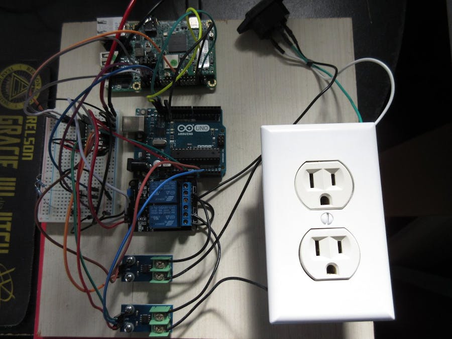
I decided to make the Smarter Smart Power Strip in fear that my wife will trip the circuit breaker on the power strip powering all my electronic stuff (computer, NAS, cable modem, router, media center, TV, external hard drives, etc.) with her hair drying/curling stuff. My wife so far has not managed to trip the circuit breaker but I think she gets close to it. As long as she doesn't have her curling iron, flattening iron, and heated blow dryer on all at once, I'm safe, but I don't want to take that chance.
Notable FeaturesThe features of the Smarter Smart Power Strip as it stands right now:
- Individual sockets will turn off their individual current draw is above a threshold.
- Priority socket shut off. Sockets with higher priority will remain on and turn off lower priority sockets when the total current draw of all sockets are above threshold. So in my use case, my wife's irons and dryers will shut off keeping my essential electronics on.
I am using a PICO-PI i.MUX6 running Android Things as the brains of the power strip. Initially I tried to run everything off this board but needed to offload reading sensors and calculating current RMS to a Arduino. The PICO-PI reads data from Arduino and determines whether or not to turn off relays.
Due to lack of resources, this project is only for 2 sockets as I only have a 2-relay board on hand. But I have written the code to easily take on more with as little modifications as necessary.
Flash the Arduino project https://github.com/bbtinkerer/I2C_ACS712/tree/master/Arduino/I2C_ACS712 to an Arduino. You can change the I2C address if you wish. This project just continually reads ADC0 and ADC1 and calculates the RMS value for an ACS712 20A that would be connected to those pins. The Arduino returns 4 bytes when requesting data from it via I2C. The first 2 bytes are in MSB format representing current in milliamps for the sensor connected to ADC0. The second 2 bytes are the second sensor.
To avoid working with live mains power lines while developing, I switched out the ACS712 sensors with 10K potentiometers. The pots can simulate what the ACS712 sensors report.
Connect the Arduino to the PICO-PI to via I2C. Also, make sure to connect a PICO-PI ground pin to a ground pin of the Arduino.
Connect a 5V power supply to the Arduino 5V pin. Make sure you are using a regulated 5V supply as you are bypassing the safety circuitry of the Arduino by powering the Arduino this way.
Connect 5V to the relay board.
Connect the relay board's ground to either the PICO-PI or Arduino.
I used a ULN2803 Darlington array to help with activating the relay board. I have 2 of the same relay boards and one of them can take direct connection to the PICO-PI and the other cannot. Instead of guessing which board can take direct connection, I'd rather just have a Darlington array instead.
Connect power to the ULN2803 chip.
Connect the PICO-PI's pins (GPIO1_18 and GPIO4_19) to input pins of the ULN2803 chip. Connect the corresponding output pins of the ULN2803 to the relay where GPIO1_18 corresponds with relay 1.
Buttons will be used to turn the relays back on if they are turned off. Connect GPIO4_21 to one side of a button. Do the same for GPIO4_22 on a second button. Connect a 10K pull up resistor on the same side of the button as the GPIO to 3.3V for each button. Connect the remaining pin of the buttons to ground.
Use Android studio to flash the PICO-PI with the SmarterSmartPowerStrip project and test with just the potentiometers for now. You should see debugging output in the Logcat window of Android Studio.
Fiddle with the potentiometers to simulate drawing too much current.
Here's a little video demoing what I have written so far.
When everything tests out okay, replace the potentiometers with ACS712 20A sensors.
From now on be Extremely Careful as mains power lines can seriously damage and kill you.
Connect the ground and neutral as you normally would to a power socket.
Connect the live wire to normally open contact of the relays.
Wire the input of the ACS712 to the middle contact of the relay. Wire the output of the ACS712 to the socket. Repeat for the second sensor.
Double check your wiring. Box everything up so no exposed mains power lines.
I don't have a box yet but when I do, I'll make sure everything is enclosed for safety and that mains power lines are isolated as much as possible from everything else.
Side NotesThe minimum current read by the ACS712 20A is 100mA, so keep that in mind if it looks like current is not read correctly. Whatever is connected may not be drawing enough current for the ACS712 to pick up.
The I2C_ACS712 project contains an Atmel Studio project to flash a similar program as the Arduino onto an Attiny85. Works when connected to another Arduino but flakes out after a second or two when connected to the PICO-PI. I will be using these in the future (when I get the PICO-PI bugs worked out) as they contain just the right amount of pins and are tiny.
Thank you for looking.


_ztBMuBhMHo.jpg?auto=compress%2Cformat&w=48&h=48&fit=fill&bg=ffffff)


Comments
Please log in or sign up to comment.