


Hardware components | ||||||
 |
| × | 1 | |||
 |
| × | 4 | |||
 |
| × | 4 | |||
 |
| × | 4 | |||
 |
| × | 4 | |||
 |
| × | 12 | |||
 |
| × | 1 | |||
Software apps and online services | ||||||
 |
| |||||
Hello! We are team Beats by dRAY! We have recently gotten our first client, who happens to be an incredibly intelligent and accomplished professor at Rice University. It is none other than Dr. Ray Simar! Unfortunately, a four-way intersection by Dr. Simar's residence has had all of its traffic lights go out, making him late to class one day. As the city of Houston is not known for its speedy road repairs, Dr. Simar has employed us to create a working model of the traffic light system for this four-way intersection, so that he can give this model to the workers and speed along the repairs. He also wants to make his neighborhood safer by incorporating an emergency system that, when activated, turns all the lights red and stops all traffic.
Luckily, we have learned exactly how to do this in our ELEC 220 class this semester! And just in case this has happened to one of your favorite professors as well, we have documented everything needed for this model to be recreated perfectly.
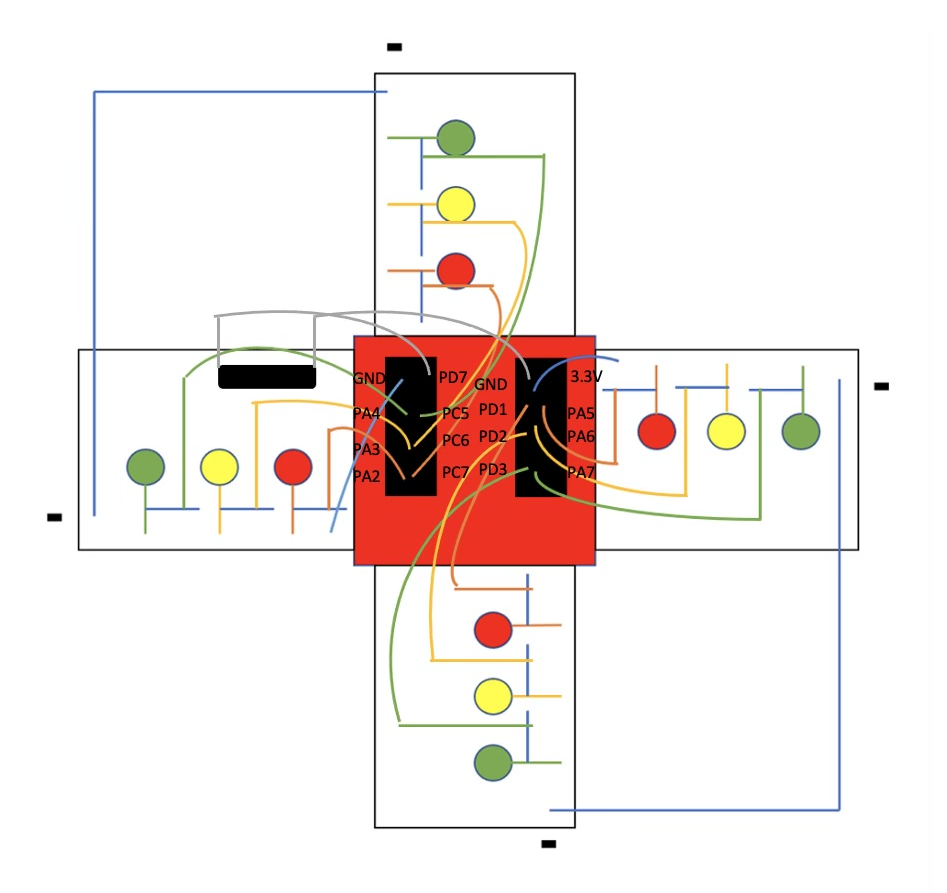
How it WorksIn this model traffic light system, each breadboard serves as the traffic light for one direction of traffic, for a total of four directions. The lights work on a timing system, where two opposing "traffic lights" each stay red for a certain amount of time, while the other two stay green. A couple of seconds before the red lights switch to green, the green lights switch to yellow for a short time. Then as the yellow lights switch to red, the red lights switch to green, and the cycle repeats. There is also an emergency system where, if the tilt switch is activated, all the lights turn red, stopping all traffic.
The BuildThe circuit for this project may look complicated, with its large assortment of multicolored wires, but no need to fear! This project is only one circuit copied onto four different breadboards, all connected to one launchpad.
First, in order to recreate this model, you'll need a few things:
- Tiva C Series TM4C123G
- Breadboard x4
- Red LED x4
- Green LED x4
- Yellow LED x4
- 10k Ohm Resistor x12
- Tilt Switch x1
- and lots of wires! (30 to be exact)
Now that you have everything you need, time to put it together.
1. Build one breadboard
First, you should build one of the four total breadboards. To do so, place the red light with the short leg in hole f6, the yellow light with the short leg in hole f15, and the green light with the short leg in hole f25. Next you should place the 10k ohm resistors by each light. These should have one leg in a hole in the same row as the long leg of the light, and the other leg in a hole five rows up the column. Then for each light-resistor combo, you should connect one wire from the leg of the resistor not directly next to the light to a port on the launchpad (port C7 for red, port C6 for yellow, and port C5 for green). You should then connect another wire for each light-resistor combo going from the short leg of the light to ground (the negative column). Finally, you will want to connect one wire going from ground to port GND.
2. Build the other three
Now that you have one breadboard, you should copy this same system three times for a total of four breadboards. However, you will only need to connect two of them to a ground port on the launchpad. Connect the other two using a wire going from the ground column on the breadboard to the ground column on a breadboard that is grounded to the launchpad.
3. Add the tilt switch
Finally, after all four breadboards are set up, the last step is adding the tilt switch. You should add the tilt switch into holes a1 and a7 on one of the breadboards. Then, add wires going from each of the legs of the tilt switch to ports D7 and 3.3V.
The code for this project was done using Code Composer Studio. It initializes ports A, C, and D on the launchpad using the helper function and a pin for each one of the lights. Then, in a while loop, 1 is added to a variable count for every loop, and, through if and else conditions evaluating count, it turns certain lights on and off. There is a copy of our code below.
The ResultAnd that's it! Now we have a working model of a traffic light system for a four-way intersection! Below is a video of the finished model.


Comments
Please log in or sign up to comment.