Hi!
I have been tasked to make a PCB for a reflow oven. Thing is, this is my first project of this sort, ever. Everything that you are going to read in this topic is what I have learned during the development and production. Hope you like it as much as I do!
Lets begin
SoftwareWe needed something that is free and functional. Meet KiCAD, your new best friend for PCB design.
Kicad offers schematics capture, PCB layout and a 3D viewer for FREE!
IdeaAs part of my apprenticeship in Semblie http://semblie.com/ , a company in Bosnia and Herzegovina for electronics development, this project got me into PCB design and the world of microcontrollers. For a company that is based on electronics and printed circuit boards it needed an upgrade on its old reflow oven.
Reflow OvenNow, as a student you do not really get a chance to see the process of reflow soldering components onto a PCB, so as many others, I have never seen such a device.
To keep it short, a reflow oven is a machine used primarily for reflow soldering of surface mount electronic components to printed circuit boards.
Reflow soldering is a process in which a solder paste is used to temporarily attach tiny electrical components to their contact pads, after which the entire assembly is subjected to controlled heat and that heat control is the main aspect of a reflow oven.
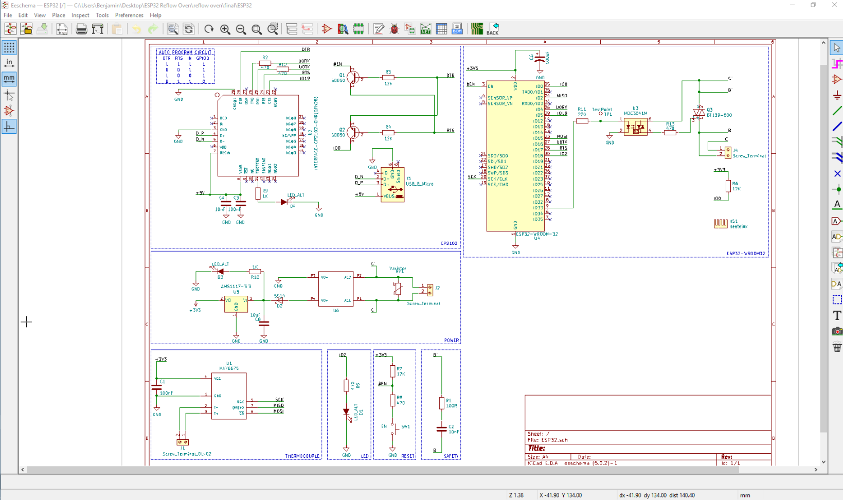
Main components that were decided to be used for the new oven.
ESP32 - WROOM -32 (MCU)
Interface CP2102 (USB-to-UART)
HLK-PM01 (AC-DC 220V to 5V)
MAX6675 (Digital Conversion for Thermocouple)
AMS1117-3.3 (5V to 3.3V)
Varistor (Circuit protection from high voltage surges)
MOC3041M (Optoisolator)
BT 139-600 (Triac)
USB_B_Micro (USB connection)
PCC-SMP-K (Thermocouple Connector)
SK-129 (Heatsink)
Diodes, switches, resistors, capacitors, jumpers and screw terminals..
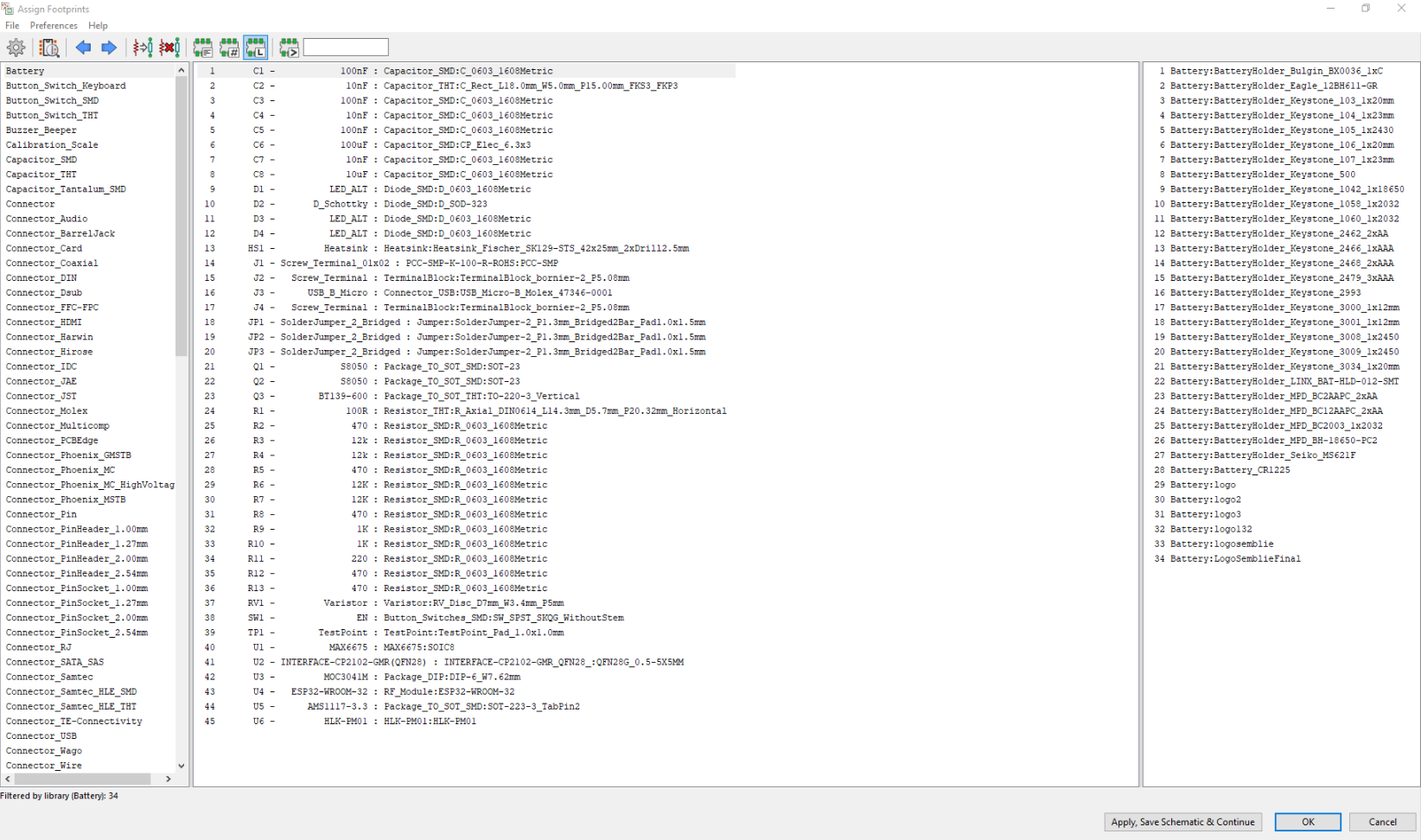
Here is the complete BoM file.
You can download it from the link provided in the attachments part.
ESP32 WROOM-32
The ESP32 is a System on Chip (SoC) designed by Espressifs systems that can be used to add both Wi-Fi and Bluetooth functionality to projects. It is ideal for the development of mobile devices, IoT applications and wearable electronics due to its wireless capabilities and smart power management among other features.
One of the project requirements were that the oven had to be connected with the surrounding systems with WiFi or Bluetooth, so ESP32 was the best choice for this job.
MOC3041M and BT-139 600
Optocouplers are great electronic devices that allow devices such as power transistors and triacs to be controlled from a PC’s output port, digital switch or from a low voltage data signal such as that from a logic gate.
Now comes the question why use a MOC3041 and another Triac together since MOC3041 already has a triac inside. The power output of the optocoupler's built in triac is around 150mW which is too low for our requirements therefor our optocouple is there to turn on the real workhorse -BT139 600.
USB and HLK-PM01 power supply. The board can function with a direct connection to a house power supply or connecting it to a laptop which gives it high flexibility.
Communication between the USB and our sugar daddy is provided by a Single-Chip USB to UART Data Transfer Bridge - CP2102 module.
AMS1117 series of adjustable and fixed voltage regulators are designed to provide up to 1A output current and to operatedown to 1V input-to-output differential. In our case, 5V to 3.3V is the name of the game.
Thermocouple Connector the PCC-SMP-K-100-R-ROHS connector for bringing thermocouple probes to printedcircuit boards.
Surge Protection
Surge protection devices protect against surges generated by electromagnetic effects, such as lightning or electrostatic discharge caused by a variety of effects.
If you wand to learn more about Varistors and Varistor calculation here is a good link
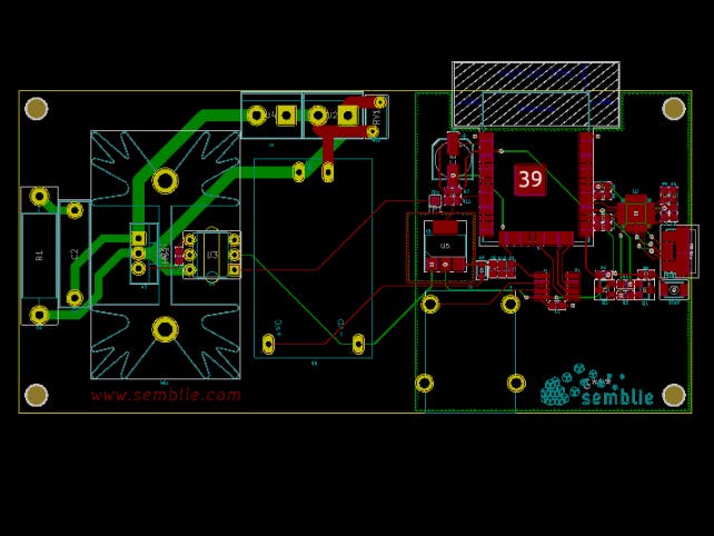
Heat Sink is your choice, however, Fischer's SK129 was sufficient for us and we made a 3D model for its footprint (big thanks to Amar Glavic ). I have uploaded the 3D model and you can download it down in the attachment part.
I have made a small 3 minute demo video for this project that covers the main aspects in the making of this new PCB.
https://www.youtube.com/watch?v=IDJE863mvNs
So that's it, you have everything that you need to create your own oven, from modules to footprints. PCB layout and design is yours to finish. You can use mine or ( I highly recommend!) play around and make your own special PCB on which you can be proud on.
In the next part we will elaborate the PID controller and the text with numbers that runs it.
See You soon
Ben.


final_Hzbd4AO0ou.png)


Comments
Please log in or sign up to comment.