Build the Circuit
Read more- Refer to the Raspberry PI Pico W pin out below
- Refer to the node connections for the mini breadboard below
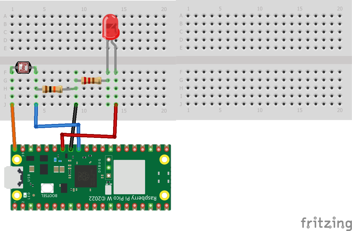
- Refer to the circuit fritzing for the LED and photoresistor below
Raspberry PI Pico W pinout
Breadboard node connections
Circuit diagram with Raspberry PI Pico W, photoresistors, LEDs, 220 ohm resistor, 10 kohm resistor
- Put the photoresistor legs on two different rows on the breadboard
- Use a wire to connect one side to the 5V VBUS
- Use a wire to connect the other side of the photoresistor to pin 27
- Put a 10 kohm resistor in the same row as the photoresistor and wire to pin 27
- Put the other leg of the 10 kohm resistor to a different wire
- Put a wire to ground from the same row
- Put a 220 ohm resistor in the same row as the 10ohm resistor and wire to ground
- Put the other leg of the 220 ohm resistor to a different row
- Put the LED in the breadboard with the short leg on the same row as the 220 ohm resistor
- Use a wire to connect the long leg of the LED to pin 28
- Create a.py file and configure it to a MicroPico project
- Write the following code and save it.
- Select Run current file on the Pico
#CAB 9.15.23 photo-led.py
#Use photoresistor to vary the LED brightness on the Lily∞Bot
#LED on pin 27, photoresistor on pin 23
#https://www.noiresteminist.com/shop
from machine import Pin, ADC, PWM
from utime import sleep_us
#define inputs and outputs
frequency = 60
photoPin = 27
ledPin = 28
photo_val = ADC(Pin(photoPin))
led = PWM(Pin(ledPin))
# set frequency of pwm signal t o60 Hz
led.freq(frequency)
print("photoresistor-LED...")
while True:
inmax = 65535
inmin = 7000
outmax = 65535
outmin = 1000
reading = photo_val.read_u16()
#mapping function (x - in_min) * (out_max - out_min) // (in_max - in_min) + out_min
scale = int((reading-inmin)*(outmax-outmin)//(inmax-inmin))+outmin
print("photo: " + str(scale))
led.duty_u16(scale)
#sleep_us(1) - Verify that the code and circuit are working correctly by watching the following video.
14 projects • 22 followers
Carlotta Berry is a Professor and Dr. Lawrence J. Giacoletto Endowed Chair for Electrical and Computer Engineering at Rose-Hulman.


Comments
Please log in or sign up to comment.