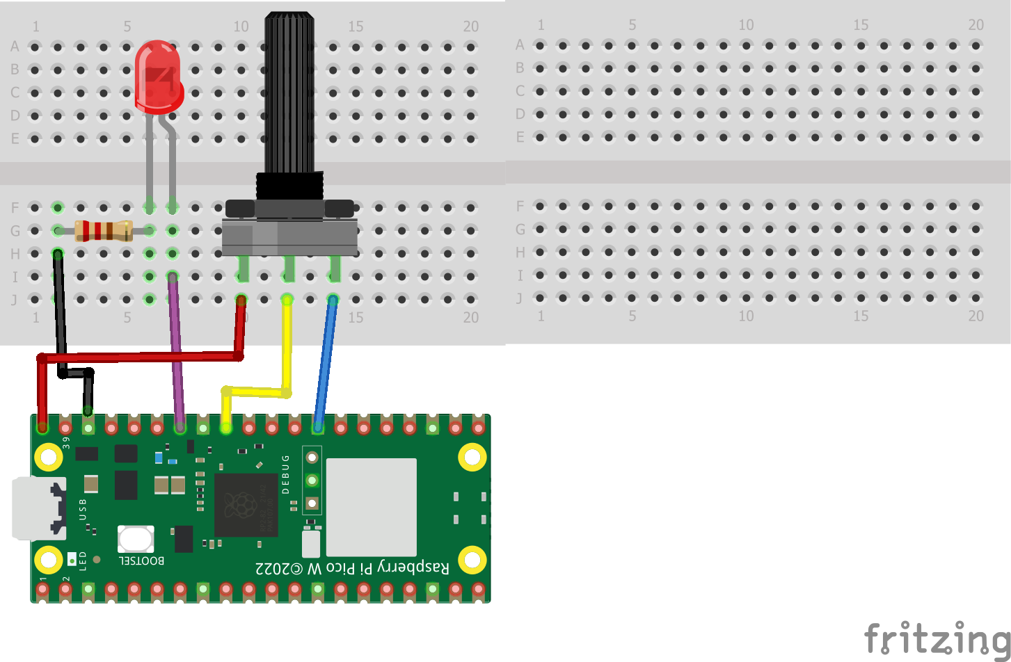
Build the circuit
Write the code
Read more- Use the following steps to build the circuit on the Raspberry PI Pico W and breadboard (see breadboard nodes and Raspberry PI Pico W pinout below)
- Put the LED in the breadboard with the short leg on the same row as the 220 ohm resistor
- Put the long leg of the LED on a different row and connect the long leg of the LED to pin 28
- Use a wire to connect the other leg of the 220 ohm resistor to ground.
- Put the potentiometer on 3 different rows on the breadboard.
- Use a wire to connect the left leg of the potentiometer to VBUS (5V)
- Use a wire to connect the right leg on the potentiometer to ground.
- Use a wire to connect the middle leg on the potentiometer to pin 27.
Tiny breadboard nodes
Raspberry PI Pico W pinout
Circuit diagram with breadboard, LED, potentiometer and Raspberry Pi Pico W
- Create a new.py file in PlatformIO Visual Studio Code
- Save the file and paste in the following code
- Use CTRL-SHFT-P or CMD-SHIFT-P to configure the code as a MicroPico Project
- Right click and run the current file on the Pico
- Note that in this code we have an analog input so we are using an analog to digital converter on pin 27 to read the potentiometer data and then scale it to values to create the blink rate for the LED.
#CAB 9.14.23 analog-led.py
#Use potentiometer to vary the LED blink rate on Lily∞Bot
#LED on pin 28, potentiomater on pin 27
#https://www.noiresteminist.com/shop
from machine import Pin, ADC
from utime import sleep, sleep_ms, sleep_us
pot_val = ADC(27)
led = Pin(28, Pin.OUT)
print("POT-LED...")
while True:
reading = pot_val.read_u16()
scale = int(reading*1000/65535)
print("POT:")
print(scale)
led.value(1)
sleep_ms(scale)
led.value(0)
sleep_ms(scale) - If your code is working correctly it should look similar to the following video.
- If it is not working correctly, try to troubleshoot and debug the circuit you built as well as the code.
14 projects • 23 followers
Carlotta Berry is a Professor and Dr. Lawrence J. Giacoletto Endowed Chair for Electrical and Computer Engineering at Rose-Hulman.


Comments
Please log in or sign up to comment.