


Hardware components | ||||||
| × | 1 | ||||
 |
| × | 1 | |||
 |
| × | 1 | |||
 |
| × | 1 | |||
Software apps and online services | ||||||
| ||||||
 |
| |||||
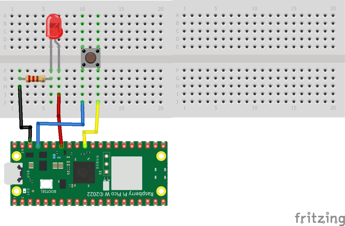
Build the project on the breadboard on the robot
Read more- Put the short leg of the LED in one row
- Put the long leg of the LED in a different row
- Put the 220 ohm resistor in the same row as the short leg
- On the opposite 220 ohm resistor leg going to a different row
- Put a wire to the ground pin on the Raspberry PI Pico W which is third from the top on the right.
- Put a wire from the same row as the long leg on the LED to pin 28 on the Raspberry PI Pico W.
- Put the button on the breadboard so that it straddles the center ditch.
- Put one wire to pin 26 on the Raspberry PI Pico W
- Put the other wire on the same side of the button to 3.3V (out) on the Raspberry PI Pico W. This pin is 5th from the top on the right.
- If you have a switch instead of a push button put each of the three pins in a different row on the breadboard. The row are marked in the first figure which represent connection nodes on a breadboard.
- Put one wire from the middle row on the switch to pin 26.
- Put a wire from either the left or right switch row to ground.
- See the Raspberry PI Pico W after the Fritzing diagram to help with the pin out.
How the nodes are connected on tiny breadboards
1 / 2 • Wiring a button and LED to the Raspberry PI Pico W
- If you have a switch instead of a pushbutton switch which is a temporary input versus a permanent one, then change the wiring diagram as follows.
- Replace the pushbutton with a switch by putting each pin in a different row.
- Connect the middle pin on the switch to ground.
- Connect either the right or left pin on the switch to pin 26 (see the figure)
- The code in the following section would be the same.
- Create a.py MicroPython file in Visual Studio
- Configure the project to be a MicroPico Project
- Type the following code in the document and save it
#buzzer.py CAB 9.14.13
#use button co control LED on Lily∞Bot
#LED on pin 28, button on pin 26
#button connected between 3.3V and pin 26
#https://www.noiresteminist.com/shop
from machine import Pin
from time import sleep
#define inputs and outputs
ledPin = 28
buttonPin = 26
led = Pin(ledPin, Pin.OUT)
button = Pin(buttonPin, Pin.IN, Pin.PULL_DOWN)
delay = 0.5
print("Button control of LED...")
while True:
print(button.value())
if button.value():
led.toggle()
sleep(delay)- Save the file
- Right click and select Run current file on Pico
- Watch the video to confirm it works correctly. If you have a pushbutton or slider switch, there may be small variations in how the code works.

14 projects • 22 followers
Carlotta Berry is a Professor and Dr. Lawrence J. Giacoletto Endowed Chair for Electrical and Computer Engineering at Rose-Hulman.


Comments
Please log in or sign up to comment.