Background
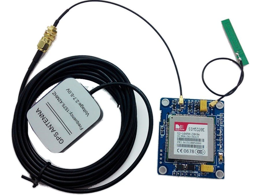
The purpose of this project is to provide directions on how to setup the DIYmall GPRS/GPS SIM5320E 3G Module so that you can issue AT commands and begin to play around with the functionality of the board.
For Arduino connectivity, I lay out two options. The first option makes the UNO act like a USB to TTL converter basically so you can communicate directly, but the UNO itself doesn't run any code. The second option uses SoftwareSerial to communicate between the computer and board.
NOTE: You should be able to use a similar approach with a different board that uses 3.3V/CMOS. You would still need 5V to power the board but you would connect the VMCU to 3.3V (same voltage as the serial connection).
Option 1 - Direct ( Arduino UNO as TTL converter )
Board Preparation (Option 1)
Disclaimer: I know this works, but I can't promise it will not cause any long term problems.
- Insert SIM card if you have one
- Connect antennas
Arduino Preparation (Option 1)
- Load an empty sketch onto your UNO (just to clear out any existing code)
- On the Arduino UNO, connect RESET to GND with a jumper. This basically makes the board act like a USB to TTL converter.
Wiring (Option 1)
NOTE: On the SIM5320E 3G board, there is a 6-pin header.
SIM5320E board <> 5V/1A power supply
GND <> GND(-)
5V <> 5V(+)
SIM5320E board <> UNO
GND <> GND
VMCU <> 5V
STXD <> D1
SRXD <> D0
Test the setup (Option 1)
1) Connect UNO to computer USB for power and data
2) Open Arduino IDE serial monitor, set baud to 115200
3) On the SIM5320E board, provide power.
4) On the SIM5320E board, two red LEDs turn on.
5) You should see "START" in the serial monitor, and you may see an error if you don't have a SIM card inserted. Type "AT" in the box and hit "Send" the board should respond "OK".
If you see the "OK" response, congratulations your board is responding!
Option 2 - SoftwareSerial
Board Preparation (Option 2)
NOTE: SoftwareSerial doesn't seem stable at 115200 baud, so the code will change the baud to 57600.
- Insert SIM card if you have one
- Connect antennas
Arduino Preparation (Option 2)
NOTE: If you did option 1, remove the GND <> RESET jumper.
- Load my sample code on your board.
Wiring (Option 2)
NOTE: On the SIM5320E 3G board, there is a 6-pin header.
SIM5320E board <> 5V/1A power supply
GND <> GND(-)
5V <> 5V(+)
SIM5320E board <> UNO
GND <> GND
VMCU <> 5V
STXD <> D2
SRXD <> D3
Test the setup (Option 2)
1) Connect UNO to computer USB for power and data
2) Open Arduino IDE serial monitor, set baud to 115200
3) On the SIM5320E board, provide power.
4) On the SIM5320E board, two red LEDs turn on. You may see some strange characters in the serial monitor.
5) Press the reset button on the UNO.
6) You should see "OK" in the serial monitor. Type "AT" in the box and hit "Send" the board should respond "OK".
If you see the "OK" response to your "AT", congratulations your board is responding!
What next?
After you completed option 1 and/or option 2, you hopefully are able to issue AT commands to your board. You should be able to find documentation for the AT commands for this SIM5320E to play around with various options.
Online AT Command Tester
I ran across an online (Java based) site that lets you issue AT commands to your board.
Link: http://m2msupport.net/m2msupport/module-tester/
From the page above, you can set your COM port (after clicking "Find Ports") and baud to connect. You should be able to use 115200 baud. Once you click "Connect" , the "Connection" in the top right will populate with the following (or something similar):
Device Model: SIMCOM_SIM5320E
Manufacturer: SIMCOM INCORPORATED
Status: Connected
Under "Diagnostics" you can play around with various commands, but be careful I don't know what all of these do! I was able to send an SMS which was a good way to ensure my GSM connection was working.


Comments
Please log in or sign up to comment.