Arduino Colour Sensing Tutorial - TCS230 TCS3200 Color Sensor || Bihari Lifehacker.
In this video we play with popular Colour sensor with an Arduino Uno. The procedure is very easy and it is an easy project which is ideal for beginners.
1) ARDUINO UNO
Arduino is an open-source electronics platform based on easy-to-use hardware and software. Arduino boards are able to read inputs - light on a sensor, a finger on a button, or a Twitter message - and turn it into an output - activating a motor, turning on an LED, publishing something online. You can tell your board what to do by sending a set of instructions to the microcontroller on the board. To do so you use the Arduino programming language (based on Wiring), and the Arduino Software (IDE), based on Processing.
Over the years Arduino has been the brain of thousands of projects, from everyday objects to complex scientific instruments. A worldwide community of makers - students, hobbyists, artists, programmers, and professionals - has gathered around this open-source platform, their contributions have added up to an incredible amount of accessible knowledge that can be of great help to novices and experts a like.
2) Colour Sensor
White light is a mixture of three basic colors known as primary colors. They are red, blue and green. These colors have different wavelengths. Combinations of these colors at different proportions create different types of colors. When the white light falls on any surface, some of the wavelengths of the light are absorbed by the surface while some are reflected back based on the properties of the surface material. Colour of the material is detected when these reflected wavelengths fall on the human eye. A material reflecting wavelengths of red light appears as red. The component used to detect colors is the Color sensor.
What is a Color Sensor?A color sensor detects the color of the material. This sensor usually detects color in RBG scale. This sensor can categorize the color as red, blue or green. These sensors are also equipped with filters to reject the unwanted IR light and UV light.
3) Display
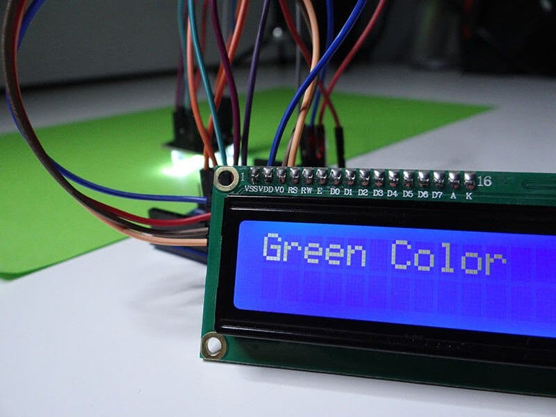
LCD modules are very commonly used in most embedded projects, the reason being its cheap price, availability and programmer friendly. Most of us would have come across these displays in our day to day life, either at PCO’s or calculators. The appearance and the pinouts have already been visualized above now let us get a bit technical.
16×2 LCD is named so because; it has 16 Columns and 2 Rows. There are a lot of combinations available like, 8×1, 8×2, 10×2, 16×1, etc. but the most used one is the 16×2 LCD. So, it will have (16×2=32) 32 characters in total and each character will be made of 5×8 Pixel Dots. A Single character with all its Pixels is shown in the below picture.
Now, we know that each character has (5×8=40) 40 Pixels and for 32 Characters we will have (32×40) 1280 Pixels. Further, the LCD should also be instructed about the Position of the Pixels. Hence it will be a hectic task to handle everything with the help of MCU, hence an Interface IC like HD44780is used, which is mounted on the backside of the LCD Module itself. The function of this IC is to get the Commands and Data from the MCU and process them to display meaningful information onto our LCD Screen. You can learn how to interface an LCD using the above mentioned links. If you are an advanced programmer and would like to create your own library for interfacing your Microcontroller with this LCD module then you have to understand the HD44780 IC is working and commands which can be found its datasheet.


_ztBMuBhMHo.jpg?auto=compress%2Cformat&w=48&h=48&fit=fill&bg=ffffff)


Comments
Please log in or sign up to comment.