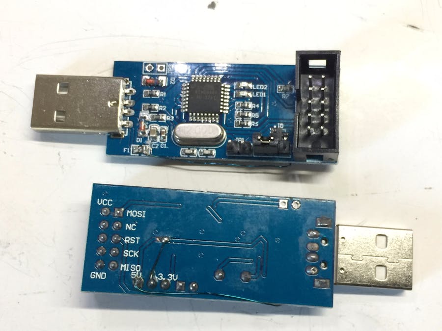
I made a half-size Arduboy with 500 games stored on a 3.3V serial flash.
To simplify the circuit and reduce the foot print, I converted the ATmega32U4 microcontroller to work at 3.3V instead of 5V.
A boot loader that works with serial flash need to be loaded to the ATmega32U4 using an USBasp programmer.
However, the conventional USBasp programmer on the market all works at 5V only.
Though some USBasp advertised that target voltage can be selected by jumper for 3.3V or 5V, most of the ones on the market can only switch the voltage of the VCC pins's but not that of the TTL signal pins such as MISO/MOSI/Reset/SCK within the ICSP connectors. These pins are still running at 5V.
From the community forums of Arduboy, I learnt that the USBasp can be modified to switch jumpers to select between 3.3V and 5V to match the voltage levels of the microcontrollers that you need to program to, both on VCC pins and also on the other ICSP pins.
However, my version of the boards were not covered in those instructions. I looked at the schematics and decided to try my luck to modify my version of the USBasp board. I hope to share my journey so you can also modify your own version of the USBasp board to work at 3.3V and 5V.
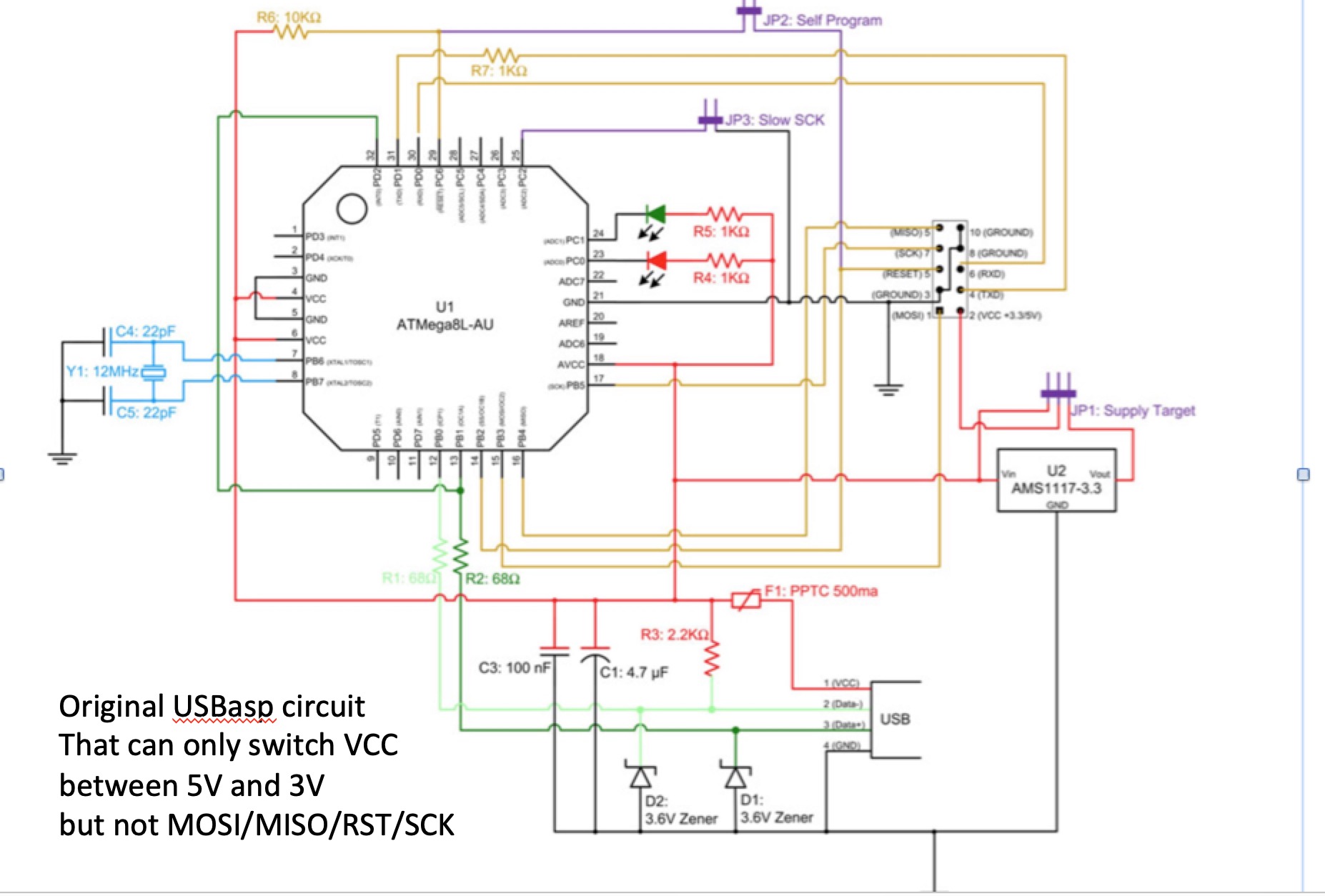
Refer to the original schematic before modification.
The USBasp is driven by an ATmega8L chip.
There is a jumper to select whether 3.3V or 5V is supplied to the VCC pins on the 10-pin ICSP connector that is used to connect to the target microprocessor to be programmed. It could be an ATmega328 for Arduino Nano, ATmega32U4 for Arduino Pro Micro (use din Arduboy game console) or ATtiny85 used in ATtiny game consoles.
However, the jumper could not control the voltage level of the ATmega8L chip. Hence all the ICS pins - MISO/MOSI/Reset/SCK are always based on the ATmega 8L's voltage level of 5V.
This could damage any microcontrollers that cannot go above 3V or any associated memory chips that only works at max 3.3V.
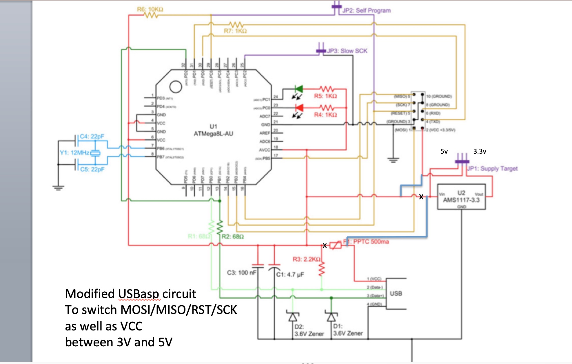
To fix this issue, refer to the second schematics (modified version), we need to allow the jumper to select the voltage level to be used by the ATmega 32u4 chip as well.
Different versions of the USBasp PCB board may need different modifications depending on the design.
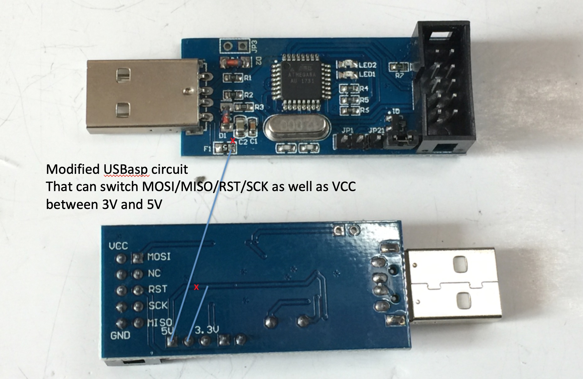
You can reference the schematics and trace the PCB board to identify how to modify the board similar to the ones below:
For my version of USBasp board, l need to cut wires/traces on the circuit board where "x" is marked:
1. In the front, right above the fuse.
2. At the back, right above the 5V jumper pin.
And add two wires (I used laminated/insulated wire of 0.3mm diameter).
3. From the 5V jumper pin to the fuse at the point before the cut.
4. From the middle pin of the jumper for 5V/3V to the point right after the cut of the 5V trace.


_PnKPri8a6q.jpg?auto=compress%2Cformat&w=48&h=48&fit=fill&bg=ffffff)


Comments
Please log in or sign up to comment.