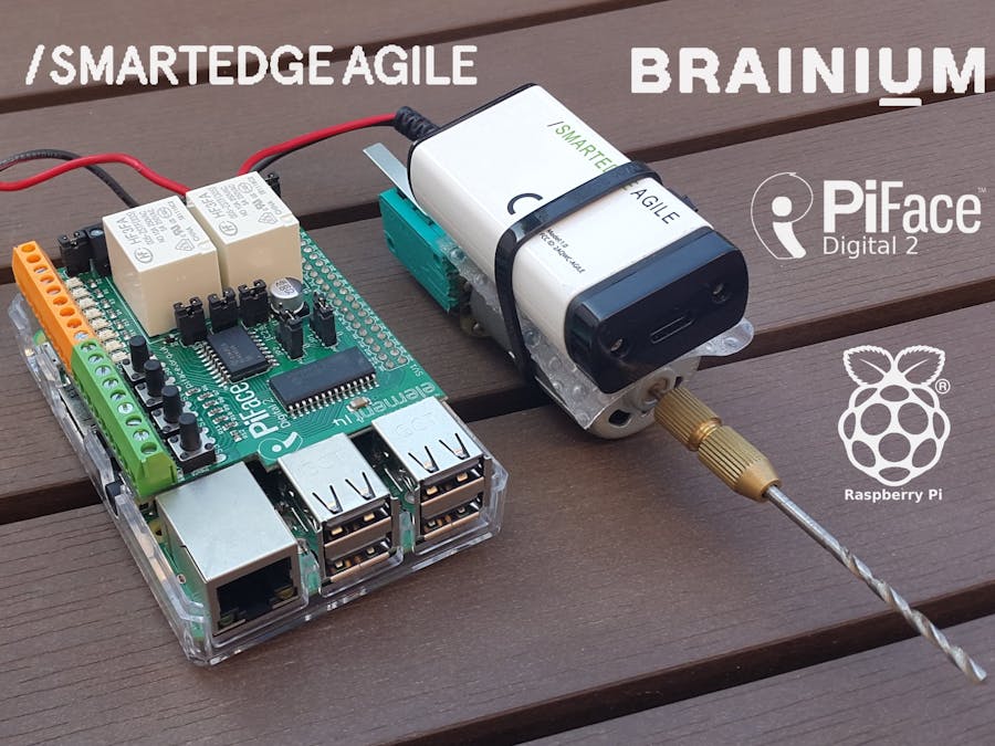
In this project I will show how the SmartEdge Agile and the Brainium platform can be used to implement an AI Powered Smart Emergency Switch device.
The Smart Emergency Switch, is a proof of concept device that acts as an emergency switch, but also learns how a device normally operates and is able to automatically detect malfunctions.
When a malfunction is detected the device is turned OFF automatically, this way possibly avoiding an accident or injury.
For the proof of concept, I used a motor used for PCB drilling, but the concept should work for bigger equipment too.
To be able to use our SmartEdge Agile device, first we need to create an account on the Brainium platform. This can be done using a web browser, by accessing https://brainium.com, and using the Sign Up button:
After a successful registration, there is a quick intro about the Brainium platform:
Next, we can download the Brainium Gateway app to our phone and use our newly created account to log into it. The phone will act as a gateway, between the Brainium Portal and our AI devices connected over Bluetooth.
The gateway should show up in the web interface too:
Now, we should be able to add our SmartEdge Agile. This can be done from the Devices tab:
The device will should show up in the Brainium app as connected:
Now we can start creating projects.
Hardware SetupFor the first experiments we will use the SmartEdge Agile device, mounted on a motor used PCB drilling:
Then we will also need a Raspberry Pi 3B+ with a PiFace Digital 2 hat on it:
To experiment with Predictive Maintenance we can access the appropriate page from the left menu bar:
When we first open the Monitor Recognition or Predictive Maintenance pages, the portal shows us a quick tutorial:
The first step is to create a workspace:
After a device to use is selected, the Initial Learning stage starts.
Initial Learning stage
In this stage the platform tries to learn how our device normally operates. It tries to identify stationary(states) and dynamic(transitions between states) patterns, based on the sensor data of the SmartEdge Agile.
In the following example, I turned the motorON and OFF multiple times. Then, I labeled the detected patterns accordingly.
In my case, the following patterns were detected:
- Motor OFF(stationary)
- Motor Start(dynamic)
- Motor ON (stationary)
- Motor Stop (dynamic)
Note: sometimes the same logical state(exMotor ON) were detected as different patterns in different time instances. As there is option to tune the learning, I decided to just label the different patterns with the number at the end(ex. Motor ON 2).
Continuous Learning stage
Once we have enough data we can generate a model for predictive maintenance:
Then we can apply the model to a device:
After this the device enters the Continuous Learningstage:
In this stage the platform still learns new patterns and detects the existing ones. Along these the platform also tries to detect anomalies, like spikes or extended dynamic states.
In the event tab we can see the generated events:
I was also experimenting with clogging the motor, to see how the system responds.
The clogs sometimes were detected as spikes / extended dynamic states, but sometimes as dynamic / stationarypatterns. Although, clogs detected as normal patterns is not optimal, we can still use them. I labeled the detected patterns with Clog 1/2/3, so later we can still identify these states as "problematic".
The Brainium platform also support creating dashboards and defining rules. To use these we need to create a project:
Dashboards
Dashboards are a collection of widgets of different types. We can create either simple widgets tracking one of the sensors of the SmartEdge Agile:
or AI widgets backed by our predictive maintenance AI model:
I ended up with the following dashboard:
AI Rules
To create an AI rule, we need to go to the Device tab, and click on the number from the AI Rules column:
When an alert is breached we will see it in the Alerts page:
Most of the data and the alerts from the above pages are also accessibleprogrammatically from the Brainium API-s. We will use these later to implement the Smart AI Powered Emergency Switch.
A Simple Emergency SwitchTo create the emergency switch we will use a Raspberry Pi 3B+ with a PiFace Digital 2 hat.
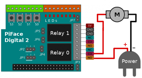
The motor and the power source should be connected as follows to the Relay 0 of the PiFace Digital 2:
An emergency switch should be hard to turn ON, but easy to turn OFF. This way we can avoid accidental turn ON-s, but the switch can quickly turned OFF in case of an emergency.
To achieve such a behavior we can use the 4 push buttons of the PiFace:
- to turn ON the switch, ALL of the 4 push buttons need to pressed exactly once(in any order)
- to turn OFF the switch, is enough to press ANY of the 4 push buttons once
4 LED (7-4) are indicating the state of the 4 push buttons, while an another LED (0) is indicating the state of the emergency switch.
The code for the emergency switch was written in Python, using the pifacedigitalio library.
The code is pretty simple. We have smartEmergencySwitch.py file with two functions:
- a
switch_pressed()function handling the events for a individual push button:
def switch_pressed(event):

   if state == "OFF":
       buttons[event.pin_num] = not buttons[event.pin_num]

       # set LED
       if buttons[event.pin_num] == True:
           event.chip.output_pins[event.pin_num + 4].turn_on()
       else:
           event.chip.output_pins[event.pin_num + 4].turn_off()

       if buttons[0] and buttons[1] and buttons[2] and buttons[3]:
          set_state("ON")

   elif state == "ON":
       set_state("OFF")
- an a
set_state()function handling the state of the emergency switch
def set_state(new_state):
   print("State: " + state);
   if new_state == "ON":
       pifacedigital.relays[0].turn_on()

   elif state == "OFF":
       pifacedigital.relays[0].turn_off()

       buttons = [ False, False, False, False ]

       pifacedigital.output_pins[4].turn_off()
       pifacedigital.output_pins[5].turn_off()
       pifacedigital.output_pins[6].turn_off()
       pifacedigital.output_pins[7].turn_off()
The next step is to add smart stop functionality to our emergency switch. To do this we can use the data and alerts from our predictive maintenance project from the Brainium portal.
The Brainium platform offers two API-s for programmatic access:
- REST API - can be used static information and historical telemetry data
- MQTT API - can be used to obtain real-time telemetry data
As we need real-time data, we will use the MQTT API.
To access the API we will need:
- an User ID and a MQTT password - these can be found under the Profile page
- a Device ID - this a unique id of form
TOXXX-0XXXXXXXXXXXXXXX- can be found in multiple pages, for. ex the Alerts page
The MQTT API offers multiple topics to subscribe for different types of data and events. I tried multiple ones, but I found the Predictive Maintenance Events topic the most suitable one.
The Predictive Maintenance Events provides events with the current state of the device and as well the anomalies detected. The MQTT topic for these events is /v1/users/{user_id}/in/devices/{device_id}/datasources/PDM_EVENT
We can use this data to implement the smart stop functionality. With the logic I implemented a problem is signaled when:
- an anomaly of type
SPIKEorEXTENDED_DYNAMICis detected - the current state is any of the known
Clogstates
When a problem is detected, the emergency switch enters a new state called ERROR. In this ERRORstate, as in the OFF state, the switch is turned OFF, but the error is also signaled by two LED-s. The emergency switch can be reset to the OFF state, by pressing any of the push buttons.
The interaction with the Brainium platform is implemented in the brainiumClient.py file. The code is based on the MQTT example from the API documentation, and uses the Paho MQTT library.
First we connect to the MQTT server and subscribe for the PDM_EVENT topic. The received events are handled in an on_message() function
def on_message(client, userdata, msg):
   print('Msg received from topic={topic}\n{content}'.format(topic=msg.topic, content=str(msg.payload)))
   decoded = json.loads(msg.payload.decode('utf-8'))
   anomalyType = decoded['anomalyType']
   stateType = decoded['stateType']
   print("Anomaly Type: " + str(anomalyType))
   print("State Type: " + str(stateType))
   if anomalyType == "SPIKE" or anomalyType == "EXTENDED_DYNAMIC" or ("Clog" in stateType):
       print("Detected anomaly")
       anomalyCallback()
In case a problem / anomaly is detected, the anomalyCallback() provided by smartEmergencySwitch.py is called. This callback changes the state of the emergency switch to ERROR.
The final Python application can be used on the Raspberry Pi as follows:
$ export DEVICE_ID="YOUR-DEVICE-ID"
$ export ACCESS_TOKEN="YOUR-ACCESS-TOKEN"
$ export USER_ID="YOUR-USER-ID"

$ python3 smartEmergencySwitch.py $USER_ID $DEVICE_ID $ACCESS_TOKEN
Here is a video demonstrating how the AI Powered Smart Emergency Switch works:
In this video, after I activated the switch, I used a cloth to clog the motor. The emergency switch detects the malfunction and turns OFF automatically.
Conclusion & Future EnhancementsWe can see that the concept is generally working, and certainly would improve the safety of a work equipment.
The malfunction detection is a little bit slow, but could be addressed if the pattern detection would run locally on the Raspberry Pi.
Cheers!


Comments
Please log in or sign up to comment.