


The project demonstrates how FM4 can write to an SD Card and how it can read back the written data. The project shows basic SD Card interface and does not demonstrate File System interface.
OverviewFM4 devices have the SDIF peripheral which allows access with external SD Card. The peripheral functions are defined as per the SD card specifications.
Requirements- Design Tool: IAR Embedded Workbench for ARM (tested), Can also work with ARM µVision IDE
- Programming Language: C for IAR
- Associated Devices: MB9B560M
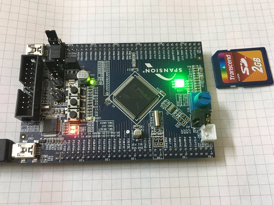
- Required Hardware: FM4-U120-9B560
No specific hardware connections are needed for this project. Ensure that the jumper settings are proper as per the guidelines given in the Kit guide. Also insert the SD card at the SD Card slot provided.
FM4 Project DetailsPDL 2.1 is used for creating the project. The SD card peripheral is turned ON in the pdl_user.h file.
The utilities folder has the necessary outer layer functions for SD card interface. These functions internally call the driver layer functions in the SDIF peripheral library to perform the SD card access. The necessary functions used are:
- Sdcard_Init
- Sdcard_Write_MultiBlock
- Sdcard_Read_MultiBlock
Here, we are making use of 1Mb of the SD card. The SD card memory size is defined by the macro TOTAL_SIZE.
Data is accessed in blocks of 4096 bytes and this is defined by:BLOCK_SZ*SECTORNUM
Each 4096 bytes sector will have one data associated with it. This means - first 4096 bytes are 0, next 4096 bytes will be 1, next 4096 bytes will be 2... and so on and the last 4096 bytes will be 0xFF (255).
The 1 Mb of SD card will be written as chunks of 4096 bytes. Data will also be read back as 4096 bytes and mutual comparison is performed in the code for the written and the read back data to ensure that data has been written correctly.
The blue LED will be toggled while write is happening and green LED will be toggled while read is happening. If the same data is read back, then the Green LED will finally glow always indicating successful operation.
If there are any failures with Write or Read, then the Red LED will glow always. Also, the code will not proceed further if there are any issues with the SD card initialization.
Note that with respect to the existing PDL (PDL2.1 on the Web), a change has been made in the interrupts_fm4_type_a file. This is to add the correct interrupt handler for SDIF instead of the dummy handler:
SdifIrqHandler((stc_sdifn_t*)&SDIF0, &m_astcSdifInstanceDataLut[SdifInstanceIndexSdif0].stcInternData);
Depending on the device used, this change has to be made in the corresponding interrupt_fm4 file.
Also few modifications are done in sd_cmd.c file.
Testing1. Before building the project, ensure that you set the paths correctly for the necessary files. See the screenshot below for IAR. The paths depend on where you save the project.
2. Build the project and then do Download and Debug. Ensure that you have inserted the SD card and it is not in the "Lock(Write Protect)" Mode.
3. Set a breakpoint at the final while(1). Now, resume the execution. If everything is proper, you will see the blue LED toggling for some time (indicating write operation) and green LED toggling for some time (indicating read operation). As now, we have read back the final chunk of 4096 bytes - the written data and the read back data both will be 0xFF. The written data will be in u8TxBuff and read-back data will be u8RxBuff. See the screenshots below:
Optionally, you can set breakpoint anywhere in the code to monitor the corresponding functionality.
Note that since we are accessing only 1 Mb, the operations will be very fast. If you are increasing the size (say to 100 Mb or more), it can take significant time to write the total 100 Mb bytes and read the 100 Mb bytes back.


Comments
Please log in or sign up to comment.