Like many people, my parents grow plants from seed in the early spring. When the seeds sprout my parents place them outside in a box with glass on top to allow the seedlings to get the sunlight they need while protecting them from cold temperatures and wind.
The baby plants stay in the box until it's warm enough outside that they will be okay on their own (about a month) and then they are planted in the garden.
The problem is that plants like a fairly narrow range of temperatures and the box can go from 50C all the way down to below freezing at night. So my parents are constantly going outside to check on them and keep them safe.
And most nights my parents bring all the plants back in the house just to make sure they are safe. The whole thing is very labor-intensive.
Disclosure: I received a free Arduino Oplà IoT Kit from Arduino to participate in this contest.
My solutionMy plan was to take a "dumb" wooden box with a glass lid and make it regulate its own temperature.
I also wanted my parents to be able to know that the plants are okay without having to go outside. Arduino cloud (with the accompanying app), and the MKR IOT Carrier gave me plenty of options for letting them know the plants are okay without going outside.
Finally, because my parents live over 100km away from me, I am excited to be able to perform remote code changes if the system needs to be tweaked after they start using it.
Here's a demo of the Smart Plant Incubator's features:
System overviewI use two temperature sensors, one inside the box and one outside. These are my inputs.
My Arduino looks at those values and can turn on a relay connected to a fan or a relay connected to an electric heat source, depending on what's required.
The temperature readings determine how the system responds:
- heat: low temp inside the box and lower temp outside
- fan: low temp inside the box but higher temp outside
- fan: high temp inside the box but lower temp outside
- off: high temp inside the box and higher temp outside
- off: the temp inside the box is okay
Here's what the whole project looks like:
(Note: I used cardboard to speed up prototyping, but that won't last outside. So I plan to move the display and other hardware into weather resistant enclosures.)
User InterfaceI had a pretty elaborate user interface in mind when I conceived of this project but I decided to make the simplest thing that could work to make it as easy to use as possible for my non-techie parents.
Design goals:
- as simple as possible
- can see the status of the incubator from at least 10 meters (so my parents can check on it from a window inside the house)
- show the minimum information required to know that the system is operating correctly
- no modes or off button. It's either on and automatically regulating the temperature inside the box or you unplug it (I didn't want a situation where my parents got the system into a different mode and then the plants died because it didn't do what they expected)
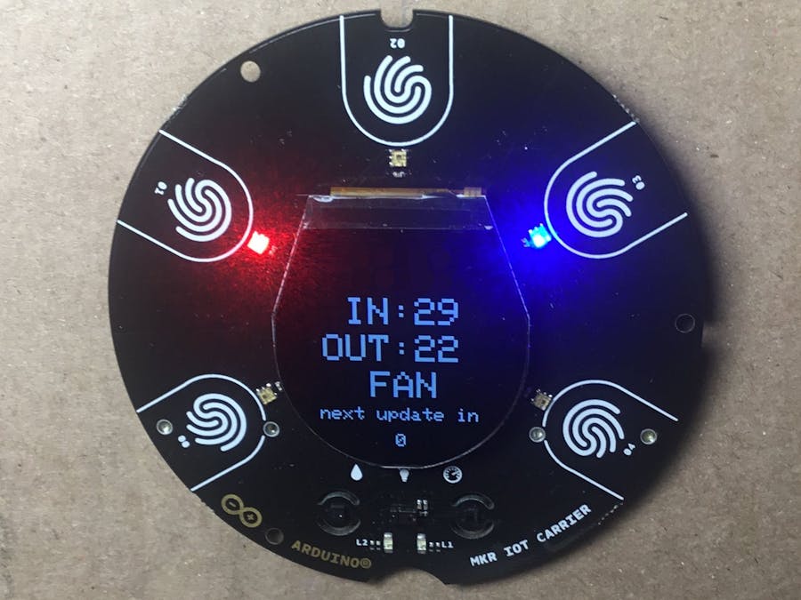
Here's what the user interface looks like:
Indicator LEDs:
I'm using two multi-color LEDs on the IOT carrier. They indicate the temperature inside the box and what action the system is taking to manage that temperature. My parents are going to use these LEDs to check on the box without going outside.
Temperature Indicator LED (left LED):
Shows the inside temperature of the box:
- error - pink (can occur if a temperature sensor returns an invalid value)
- way too cold - blue, flashing
- cold, but not dangerous - blue
- okay - green
- warm, but not dangerous - red
- way too warm - red, flashing
Action Indicator LED (right LED):
Shows what action the system is trying to take to regulate the temperature inside the box:
- error (no action) - pink (can occur if a temperature sensor returns an invalid value)
- cooling - blue
- warming (either by fan or resistive heating) - red
- no action - green
Display:
The display shows the following information:
- inside temp
- outside temp
- the current action
- the time (in seconds) until the action is recalculated (dynamically adjusted to prevent overshooting the target temperature)
Arduino IOT Cloud Dashboard:
Again, my goal was to keep everything as simple as possible.
Here's what it looks like:
The current inside and outside temperatures are shown on gauges.
The historical temperatures are shown on time series plots. As you can see, the inside temperature is being held around 22C by the heater, despite the fluctuating temperature outside.
And the other widget shows debugging information that I may need to diagnose problems remotely.
Demo ModeYou can use the serial monitor to put the system in a "demo mode" where you can override the temperatures coming from the sensors.
This allows you to get the system into states that would be hard to do with the actual sensors (like -50C inside and +50C outside) and see what it does.
This mode is only used for development and debugging.
BuildMKR-1010 and theIOT Carrier:
The IOT Carrier uses most of the pins on the MKR-1010. And I the only way I could be sure the carrier didn't interfere with the I/O I needed for this project was to isolate the pins I need on the MKR-1010 pins from the carrier.
I inserted female headers between the MKR-1010 and the carrier for the pins I wanted connected between the boards. The pins without female headers between the boards are isolated. You can see pins A2-A6 are isolated in the following photo:
D7 is isolated on this side of the board (it's not visible in the photo below but I broke the pin off the female header at D7 on this side).
I soldered the wires I need to control my project to the male headers and inserted them into the MKR-1010.
Power, relays, and terminal block:
I organized the equipment that should be outside the box as shown in the photo below:
TheTerminal Block:
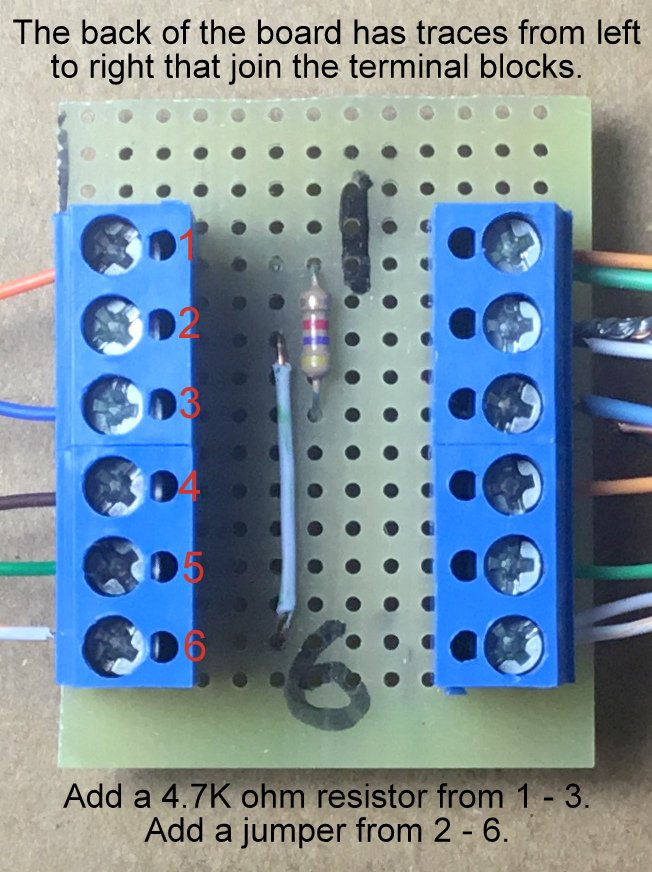
The wires from the MKR-1010 go to a terminal block so I can take the system apart for transport and storage.
The schematic section shows you how to build this part.
Here's what all the wires do:
(Note: there are traces on the back side of the board that run from left to right and connect the terminal blocks together. See the schematic for more info.)
Temperature Sensors:
There's one temperature sensor inside the box and one outside the box. They are positioned so the sun will never directly shine on them and skew the readings.
Here's what one of the temperature sensors looks like:
I prefer to mount the temp sensors on little boards I make so I can easily replace them or recover them for use in another project. But it's perfectly fine just to solder them directly to your wiring harness (just don't overheat them).
(Note: while these sensors are awesome to work with, they don't always give the same readings. So, I set up 6 of them on a breadboard and choose two for this project that read the closest to each other over a range of temperatures.)
The CoolingSystem:
The fan is located at the long end of the box. Here's what it looks like:
The fan blows air out of the box.
I may add a strip of flexible plastic over the fan on the outside of the box to prevent air from moving in/out of the box when the fan is off. The fan will push the plastic out of the way when it turns on.
(Note: I didn't add ventilation holes to the other end of the box yet. I want to see how well it performs in actual operating conditions before I make more holes in the box. It's possible that air leaks around the box and between the box and the glass may provide enough ventilation on their own.)


_1x_bGT19vVAby.png?auto=compress%2Cformat&w=40&h=40&fit=fillmax&bg=fff&dpr=2)
_3u05Tpwasz.png?auto=compress%2Cformat&w=40&h=40&fit=fillmax&bg=fff&dpr=2)
Comments
Please log in or sign up to comment.