Are you a fitness lover and would push yourself to the extreme everyday when you are in the gym? Have you ever forgotten how many reps you've done after 20~30 push-ups or lunges?
UpFit to the rescue.
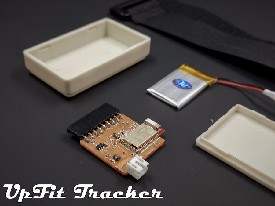
With UpFit, you will never have to count the reps yourself. Just wear the UpFit tracker device and open the mobile app, and you are ready to go. Dig deeper with maximum reps you can, listen to your favorite workout playlist, sing alone the way and check back the app at the end for today's number you've got.
How to UseHardwareThe hardware design I had in mind was quite challenging to me. I wanted to make a custom wearable board design to minimize the size of the device. This means I'll have to resolve couple of things:
- What platform should I use? Arduino, mbed, or use Infineon DAVE?
- Home made PCB and solder the BLE module and the tiny LGA-8 package DPS310 chip.
- How to prototype and how to program the final product?
There were other unexpected challenges, I'll cover them later.
So here was my plan to step by step implementing my concepts:
- Make a DPS310 breakout board - Make sure Othermill Pro is capable of making the PCB, and I can hand solder the DPS310 chip.
- Choose Bluetooth module - Easy to prototype and convenient to migrate the design to a custom board.
- Prototyping with dev board
- Make custom board
First thing first, I'll need to make sure I can make a PCB and solder the DPS310 chip. I own an Othermill Pro and I planned to use that to make the breakout board for prototyping.
Although the dimension for LGA-8 package is well blow the minimum size mentioned in the official Othermill spec, but based on my previous experience with it on the PCBs for small form factor chips, I believe this is still doable.
I found the footprint for DPS310 on a website called SnapEDA. This seems a very helpful website offers a lot of footprints for many devices that you commonly couldn't find their Eagle libraries.
Here is a helpful video taught me how to proper solder LGA package chips.
And here are my finished breakout boards for DPS310, it turned out to be a success! And this was my very first time solder chips with this fine pitch, I'm happy with this result.
After a quick search I found Infineon has already provided an Arduino library to work with this chip! So I just wired up the breakout board with Arduino through I2C, and it worked like a charm!
Time to move on to next step: choosing our Bluetooth module + microcontroller.
Choose Bluetooth moduleThere are quite a lot of Bluetooth module out there for makers, but really which one is the best suit for my case? Here are my criteria:
- There must be an Arduino compatible dev board available so I can prototype with least effort.
- It also have to be available as a standalone module so I can reduce the size of my final design by solder the module directly on my PCB instead of using headers.
- The module must have a PCB antenna or chip antenna built in so I don't need to waste time on the RF design.
- Last, the module should easily be programmed.
OK, let's review what I have in my arsenal:
(nRF51822 based BLE module)
- Adafruit Feather M0 Bluefruit LE (MDBT40 module)
This is not suitable because the program is running on a dedicate microcontroller which means one more component in my final design.
- Adafruit HUZZAH32 (ESP-WROOM32 module)
This may works, but to handle it may beyond my project scope. The main drawback was that the module come with HUZZAH is preloaded with Adafruit's custom bootloader to support Arduino program. But the ESP32 module you bought separately don't have that bootloader, so you will need to know how to download the bootloader first before you can migrate. This is something sounds intimidating to me for this small project.
- Espressif ESP32 Dev Board (ESP-WROOM32 module)
I didn't choose this because it doesn't support Arduino out of the box.
- Adafruit Feather nRF52 Bluefruit LE (MDBT42Q module)
Similar to HUZZAH32 case, you will need to program the module to run custom bootloader before you can flash Arduino programs on to it.
- RedBear MB-N2 + Blend v2 / Nano v2 (Chosen Solution!)
This was my chosen solution. You can easily see the different tiers RedBear offers via this series of boards/modules. Here was my plan:
- Use Blend v2 Arduino board + my DPS310 breakout board to prototype my firmware quickly.
- Use Nano v2 as the pre-production design to verify it will work on Nano board as well.
- My final design would based on the nano design, and put the MB-N2 and DPS310 together into my custom PCB.
So far so good. Let's move on to prototyping.
Prototyping with dev boardPretty simple, just wire up the breakout board with Blend v2 board via I2C, and program!
So we have Arduino compatible BLE dev board, we have the DPS310 breakout board worked with the Arduino UNO board, we have the DPS310 Arduino library, what could go wrong?
Yes, it could. And it did: The DPS310 Arduino library seems only works with UNO and some other board that use the same Atmega328 microcontroller. If you use the library with other microcontroller, it will most likely cause compile error.
The root cause of that was the way the DPS310 library using the Wire library is not universally available in Wire libraries implemented for other microcontrollers.
The problematic method only available in AVR Wire library:
uint8_t TwoWire::requestFrom(uint8_t address, uint8_t quantity, uint32_t iaddress, uint8_t isize, uint8_t sendStop)
In Wire libraries for other platforms, the only available requestFrom function is declared with two parameters:
uint8_t TwoWire::requestFrom(uint8_t address, uint8_t quantity)
Here is how it was used in DPS310 library:
int16_t IFX_Dps310::readBlock(
    uint8_t regAddress, uint8_t length, uint8_t *buffer) {
  //request length bytes from slave
  int16_t ret = m_i2cbus->requestFrom(
      m_slaveAddress, length, regAddress, 1U, 1U);
  //read all received bytes to buffer
  for(int16_t count = 0; count < ret; count++) {
    buffer[count] = m_i2cbus->read();
  }
  return ret;
}
But this can be easily fixed with some workaround code. What those two extra parameters does was write the register address iaddress of length isize before it start requesting from I2C slave. So I modified the DPS310 invocation code to call the three parameter version after writing one byte address manually:
int16_t IFX_Dps310::readBlock(
    uint8_t regAddress, uint8_t length, uint8_t *buffer) {
  m_i2cbus->beginTransmission(m_slaveAddress);
  m_i2cbus->write((uint8_t)(regAddress));
  m_i2cbus->endTransmission(false); // Don't perform STOP on the bus.
  //request length bytes from slave
  int16_t ret = m_i2cbus->requestFrom(m_slaveAddress, length);
  //read all received bytes to buffer
  for(int16_t count = 0; count < ret; count++) {
    buffer[count] = m_i2cbus->read();
  }
  return ret;
}
And then there are other catches: I2S is not implemented using the same header file as in AVR version, so the I2S code in the DPS310 library doesn't work as well. I'm only using the I2C part, so I just removed unused code from the library.
You can find the final firmware source code including the modified DPS310 library from my github repo.
After some additional includes and small modifications, the library finally compiles. And it worked! And it worked on Nano v2 as well!
It's time to make our own PCB!
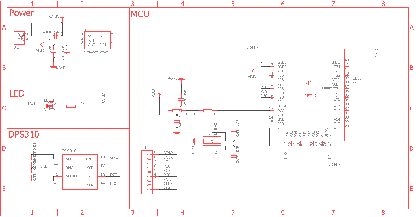
Make custom boardMy first attempt was to make a breakout board for the MB-N2 module and see if that's the only component I need in my final design. I'm glad I did that, because it turned out I will need some extra components, specifically the LC filter circuit for the DC/DC converter, and external 32.768 kHz crystal oscillator as the low frequency clock input of the nRF52832 chip.
Following are the diagrams copied from datasheet of MB-N2 and nRF52832, indicates those extra components and why they are needed:
I don't have all the components in hand, so what could I do? Salvaging the components from the Nano v2 board! And this decision also simplified my PCB design work a lot because I can just modify the Eagle file for RedBear Nano v2 by removing some unnecessary components and add DPS310.
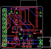
I listed my Eagle design in the schematic section below, and you can find the original file from my github repo.
My board design went through three revisions.
- The first one I made had all the ground pins of DPS310 unconnected.
- The seconds one connect DPS310 to wrong pins of MB-N2. The pin number used in Arduino is different than the actual nRF52832 pin number and I got that wrong when design the board.
- The last one finally works.
Here is the final board I assembled with a hot air rework station and solder iron.
To program this board, I used the RedBear DAPLink v1.5 board. It is an interface board supports both drag-n-drop and Arduino flashing the program to the MB-N2 board.
Here is how the board is connected to DAPLink adapter.
The mobile app part of the project is responsible of converting the pressure change pattern into vertical movement counter. Traditionally this was done by using the accelerometer data, but forgive my poor background knowledge of accelerometer, that looks complex to me at a glance. But what I employed in my algorithm here was simple because the pressure value is roughly proportional to the altitude change within certain range. In the case of detecting the workout movements, we are talking about couple of inches, which can be definitely seen as be proportional. So here is my algorithm to detect push ups, which typically is a 4~5 inches vertical movement (translate into around 1 Pa pressure change):
long pressure = getPressure(characteristic.getValue());
long diff = pressure - lastPressure;
lastPressure = pressure;
if (Math.abs(diff) > 4) {
  // not a push up.
} else if (Math.abs(diff) >= 1) {
  // There is some vertical movement
  if (diff > 0) {
      isUpwards = false;
  } else if (!isUpwards) {
      isUpwards = true;
      ++number;
      textView.setText(Integer.toString(number));
  }
}
My original idea was to use Ionic + Angular for quick proof of concept. It did work on BLE scanning, connecting to the device and receive data from the device, but there was one major problem: the performance of the Javascript is so bad that the UI thread won't able to handle the Bluetooth data communication while update the UI so the UI would just frozen all the time. The solution for that would be enable service worker to handler BLE communication, but that beats the whole purpose of using the Ionic to do the fast prototyping by adding too much complexities. So I turned to a native Android solution.
By using the native solution, I was hoping that at least running the BLE communication in the background would be a easier task to do. But as it turned out the native app could even handle the communication in the UI thread without any trouble. This simplified the coding complexity quite a lot and I get the numbers displayed in just couple of hours.
You can find the Android app source code from my github repo.
ConclusionDPS310 is able to measure the pressure change very accurately, this opens up a lot more applications that traditional pressure sensors aren't capable of. Using the measured pressure change and converted it into vertical movement counter leverage the nature of correlation between the pressure and altitude, and simplified the detecting algorithm a lot.
From hardware design perspective, I found the DPS310 very easy to use. The tiny form factor makes the space-limited design like the wearable devices possible. It's easy to work with as it only requires two capacitors to work with. Built-in I2C makes it require very few connections, and provide high precision results.
Further Improvements- Track multiple workouts.
- Store workout history.
- Increase the precision of the measured pressure data. Pa is coarse for workout movements. I plan to use raw data to measure the movements.


Comments