


Hardware components | ||||||
 |
| × | 1 | |||
Software apps and online services | ||||||
| ||||||
WHY would anyone want to measure the voltage of the power supply connected to a microcontroller and to ATtiny85 in particular?
I was working on a project where a solar cell chargeda battery, and a servo motor turned the solar cell towards the sun using a photoresistor in order to optimize the charging during the day. It turned out that during certain periods (e.g. night or darker days), power dropped so low that the entire system stopped working correctly. One of the solutions was to stop using the servo motor when it was dark outside.
This would’ve been the perfect solution, but the solar-charged battery powers another system – a water irrigation unit with a pump, which makes the problem a little bit more complex. So, I thought that I would measure the power supply voltage that comes from the solar cell, and when it drops too low, the water pump and the servo motor will not start until the power goes up again.
So, that was the motivation to work on that.
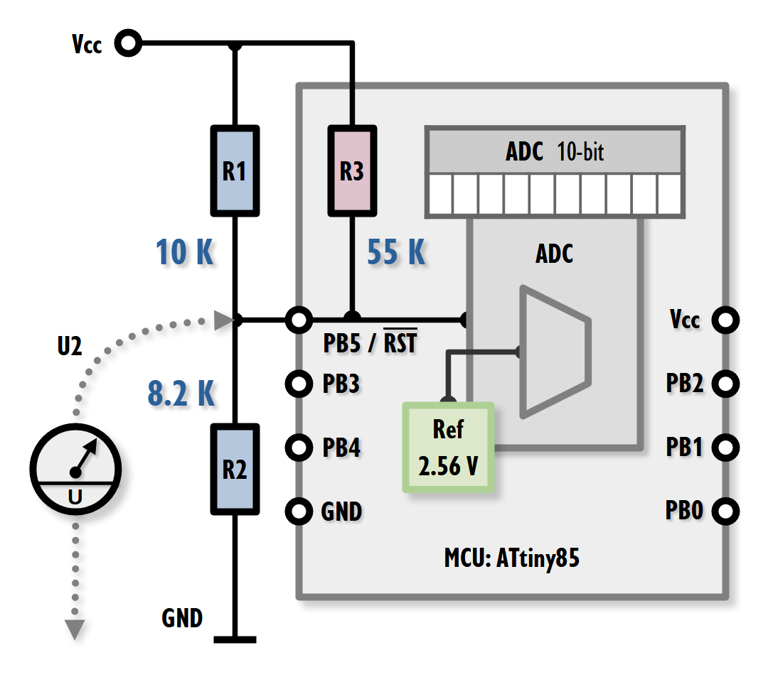
Choosing the port and ADC channelOn my microcontroller setup – a Tinusaur Main Board, I already have a 10 K pull-up resistor on the RESET pin. This also happens to be the PB5 port, but it is not used as such in my setup. The same I/O pin could also be used as analog input ADC0. What is interesting is that the ADC0 can be used even when the pin is used as RESET.
The only requirement is that the voltage on that pin does not fall below a specific value – otherwise, the microcontroller will be reset. To be safe, I decided this value to be 2.6 volts.
Choosing reference voltage for the ADCChoosing Vcc as a reference voltage source makes no sense because as the power supply voltage changes (i.e. the Vcc), the measurement will change equally.
Choosing 1.1V as a reference is not very practical because it is too low.
So, I chose 2.56 V as a reference voltage for the ADC0.
Since I already have a 10 K pull-up resistor on the ADC0, I needed a pull-down resistor also in order to create a voltage divider. After some calculation and a lot of experiments, I decided that 8.2 K is a good value to work with. I also decided that I should use only 1% precision resistors.
This schematic would’ve worked just fine if there were no some specifics in the internal ATtiny85 schematics.
If we assume that the voltage divider consists of only the R1 and R2, we will be wrong. In fact, there is an internal pull-up resistor connected to the RESET pin when the pin is used as RESET. The value of this resistor is not very precise, but for the purpose of this particular setup, we will assume that it is approximately 55 K.
The compound value of the resistors R1 and R3 connected in parallel is 8.46 K.
How do I know that?How have I figured out that there is an internal pull-up resistor?
Before doing my research on the original ATtiny85 datasheet (like everyone should do), I did some experiments and measurements which I later compared with calculated results. Because they were very different from each other I came to the conclusion that there must be something changing the parameters of the voltage divider. So, I decided to read the datasheet. 📷
Measurements vs CalculationsAfter I had my assumptions, schematics and parameters straightened up, I did all the measurements again and compared them with the calculations.
The differences were only -3 to +3, which could be an error on the power supply source or the multimeter that I used.
I resolved to go with the calculated values, which are listed below.
The table with the values can be found here: https://tinusaur.com/tutorials/vcc-measure-on-adc0/ (sorry, couldn't create a table here)
For a power supply voltage above 5.2 V, the ADC will always give 1023, which is the maximum value for the ADC.IMPORTANT NOTE: The ATtiny85 microcontroller should not be powered by more than 5.5 volts. (ref.: datasheet)
For a power supply voltage below 2.56 V, the ADC will not measure it correctly because it falls below the reference source voltage.IMPORTANT NOTE: The ATtiny85 microcontroller should not be powered by less than 2.6 volts. (ref.: datasheet)
Source codeTo work with the ADC on ATtiny85 I use the ADCX module from the TinyAVRLiblocated at:
An example code could be found in the “tinyavrlib_adc0_pow1” module.
Here are the basic steps:
adcx_init(); // Init the library
ADCX_ADCSEL(ADCX_SELECT_MASK_ADC0); // Select ADC channel
ADCX_REFSEL(ADCX_REFSEL_MASK_INT256V); // Select reference voltage
_delay_ms(ADCX_CHANGE_DELAY); // Small delay after change
ADCX_START(); // Start ADCconversion
uint16_t adcx_result = adcx_read(); // Read ADC0 valueIt is possible to measure the power supply voltage on the ADC0 input using a voltage divider, and it works well if we don’t need high accuracy.

Comments
Please log in or sign up to comment.