


Hardware components | ||||||
| × | 1 | ||||
| × | 1 | ||||
| × | 1 | ||||
| × | 1 | ||||
Software apps and online services | ||||||
 |
| |||||
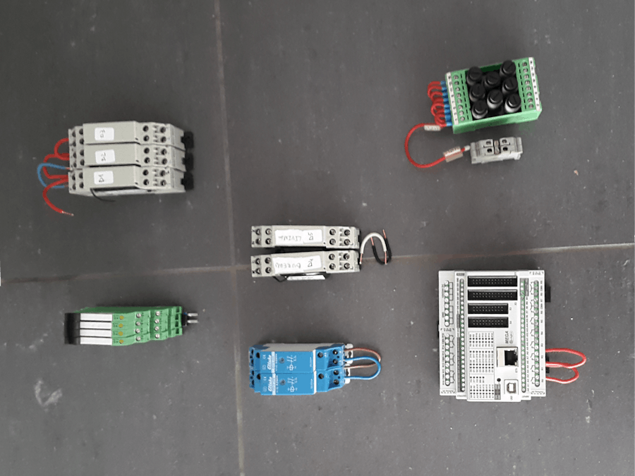
The old home automation system of my house was due for a replacement in order to add new functionality and get rid of some limitations and bugs. The original system was running on a mitsubishi FX2n PLC (old school). Here's an image of the setup:
The PLC is responsible for reading out activity on the 'input' channels' and dispatching this to one or more of the output channels. Example: when the button attached to input 1 is pressed, the light attached to output 3 has to be toggled. It also contained a couple of timers that would automate things such closing the roller shutters every day at 20:00 (very inflexible).
ProblemUnfortunately, it could not be connected to the internet and the code on the plc system was hard to change, which had to be done in order to fix a couple of bugs, support some new inputs/outputs and for making the automations a bit more flexible.
SolutionHardware
I opted for an approach that re-uses most of the current installation, but improves the outdated parts. This means that the PLC unit has to be replaced with a new version that:
- supports a connection to the internet in some form
- can easily be programmed in a language/system that is widely known and supported.
Luckily, the Contrillino PLC unit can do both: it has an Ethernet connection and can be programmed in standard arduino C.
The 'mega' version also provides:
- 16 230V/6A relays
- 21 analog/digital inputs (24/12V DC)
- 24 digital outputs (24/12V DC)
Software
The software has the following features:
- the controllino firmware is generic and configurable: different button types can be selected (push or toggle buttons + analog) and inputs can dynamically be linked to outputs.
- an android application is used to configure the firmware.
- an other android application functions as a dashboard for remote control
- The AllThingsTalk cloud platform is the glue that puts everything together, it also provides automation and a developer interface.
If you would like to build a similar solution for you own house, I propose the following approach:
Before you build the end solution, create a prototype:
- Prepare the firmware and cloud
- Do the wiring
- Configure your unit and remote
Once you are happy, build the final solution:
- Study and learn the old schematics
- Make a wire diagram
- If you haven't already: prepare the firmware and cloud
- Do the wiring
- Configure your unit and remote
- Prepare the cloud
Before uploading the firmware to your controllino, you should set up the cloud part of the solution:
- Create an account on AllThingsTalk.
- create a new device: click on 'connect a device', select 'custom' and provide a name for your controllino unit.
After creating the device, you will be presented with a 'setup' page that shows your credentials. You'll need those in the next step.
- The firmware
Next, it's time for the firmware:
- Download it from github
- rename the file 'example_keys.h' to 'keys.h'
- open 'keys.h' and fill in the credentials of your device (see 'prepare the cloud')
- open the file 'controllino_lights_control.ino' with the arduino ide and upload it to the controllino (make certain you install and select the controllino board).
- reboot the controllino or open the serial monitor in the arduino IDE
Once the firmware is running, it will automatically create the initial assets for the device in the AllThingsTalk application. When this is done, you are able to start using the mobile applications (see further).
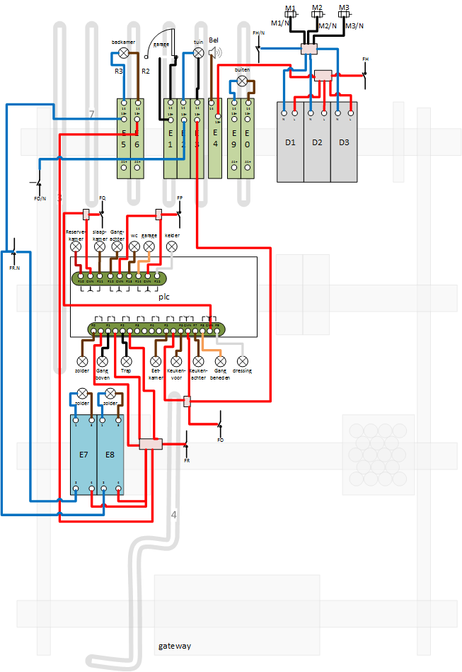
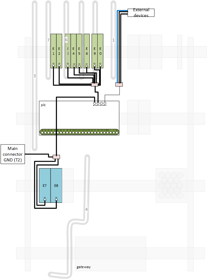
- Make a wire diagram
I can't stress this enough: before you begin to hook up all the wires to your PLC unit, make certain you have prepared a wire diagram that shows every connection made on the controllino. This way, you can find wiring problems before they actually occur and it allows you to move really fast once the actual job starts.
You'll see plenty of wire schematics in this post which can serve as an inspiration. It doesn't really matter how you make them (can be with pen and paper if you like), as long as you have some kind of plan layed out before you begin.
Also, make certain that you include a 24VDC or 12VDC power supply to feed the unit. I've also included a bunch of fuses, which came with the original installation. They are great for separating all the consumers (PLC, buttons, leds,..) from each other and the power supply.
- Wiring
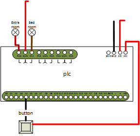
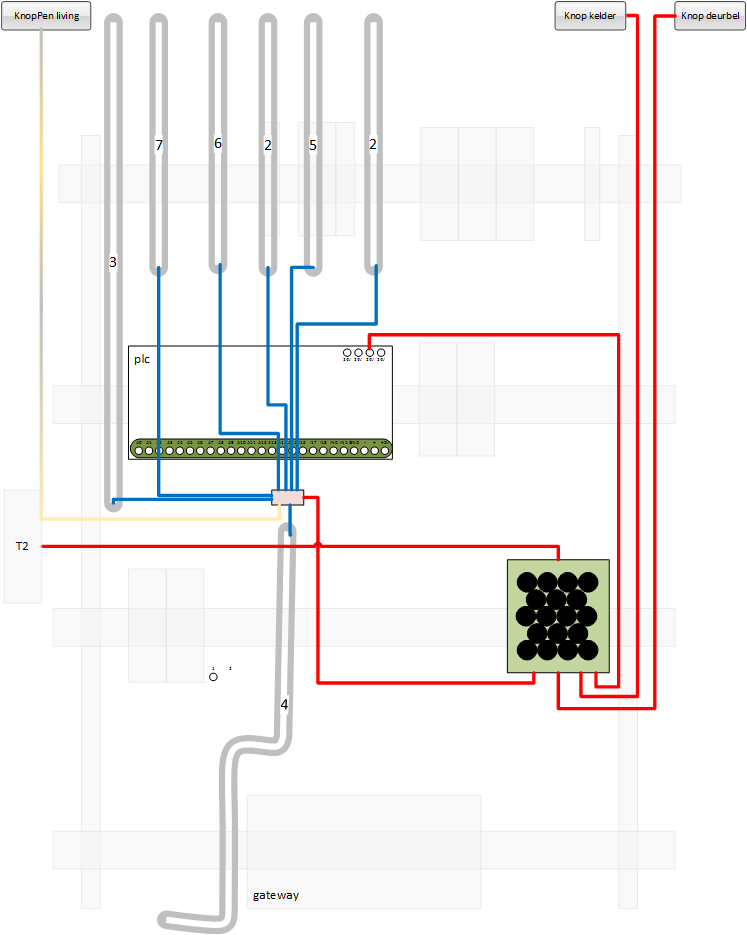
The wiring in the house is set up as a star diagram where all wires come to a central 'control' point. The following diagram displays this in a most basic way:
All buttons and lights (also a doorbell, gate and others) come together at a central point from where they can be patched.
Lights are connected to the controllino through the relays lines. Each relay on the controllino can disrupt/close a single wire. So, in order to control a light bulb, you need to break 1 of the wires going from the switch box to the light, as shown in the following image:
As the controllino runs on 24V or 12V, that's the voltage which has to be received on the inputs connected to the buttons. This makes them the switches in your house pretty save (you won't get electrocuted if something goes wrong).
The power for the buttons can come from one of the controllino's 24V pins, as shown in the basic diagram, but as already mentioned, it's better to use a fuse and separate the different power consumers, shown in the 'power supply' diagram.
To get your feed wet, you can try out building a similar setup as shown on the basic diagram from the schematics section. It's just a basic setup for 2 lights, 1 switch, power and ground for the controllino.
CAUTION:
- always turn off the main fuse before doing any work on the electrical system of your house. Getting fried is no fun.
- If you'r uncertain about something, first ask a professional
- label your wires. Very important: label your wires.
- take pictures, lots of them. Just in case you screw something up.
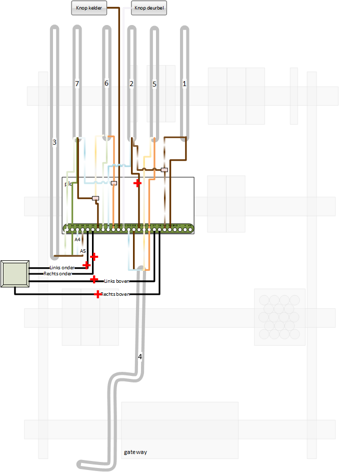
Once you are comfortable with the system, you are ready to start working on all the wire connections. Some sceneries:
As you can see, thanks to the new system, a lot of components were no longer needed and plenty of room came available in the switch box. Some of that room will be used in another project, for a secondary, 'higher level' module.
- Configure the PLC
Before you can use the system, the controllino application needs to be configured: you need to tell it what button goes with witch light. This can be done with the accompanying mobile app. Currently, there is only an android version available in binary format.
But, it's python, so it can run it as a desktop application or you can also compile it for an iphone (with the proper equipment).
Every output/relay channel is represented by a box like so:
- 1: the number of the output or relay
- 2: a button to activate/deactivate the line. The output can only be controlled if it's active.
- 3: a button to change the current state of the output (toggle it on/off).
- 4: a Led to indicate the current state
- 5: an input box so you can give it a name.
Each input line has a similar control box:
- 1: the input line number
- 2: a drop-down for selecting the input mode: off, toggle, push button, analog
- 3 a drop-down for selecting the output that the input line controls. This allows you to specify multiple buttons for a single light.
- 4: the current status of the input line, aka: is the switch pressed or not (useful for finding the buttons in your house).
- 5: an input box for labeling the input line.
Although this application allows you to control the outputs, it's interface is not ideally suited for daily remote control. That's best done with the next app.
- Configure the remote control app
As a final thing, it would be nice to have a configurable remote control. You can do this with the following app. It's actually a generic dashboard builder/utility that works with the AllThingsTalk platform.
To create a dashboard:
- log in with your account credentials.
- Create a new group (click on the + sign), call it 'lights' and select the desired icon.
- Create a new section (click on the second + sign) on the page and call it 'downstairs'
- Add a new control (click on the third + sign)
- select it's asset
- provide a label
- select the control and skin (when available)
- set the desired scale
Click on the v in the top right corner to save your creation and you are ready to go.
Here's a screenshot of most of the currently supported controls (labels and text boxes are missing).
Building a home control system like this using the controllino was fairly strait forward, once you know how to do it. It's like a big puzzle of wires, just follow the drawing and you'll get there. Most of my time went into the preparation: write all the code, get it stable (very important), figure out how the old system worked, understanding every wire, drawing the schematics... The actual patch work was done in 1,5 days.
If you like to undertake a similar operation, I hope this guide and set of tools will help you save a lot of work...
Next up: more automation with z-wave and events
a basic diagram


Comments
Please log in or sign up to comment.