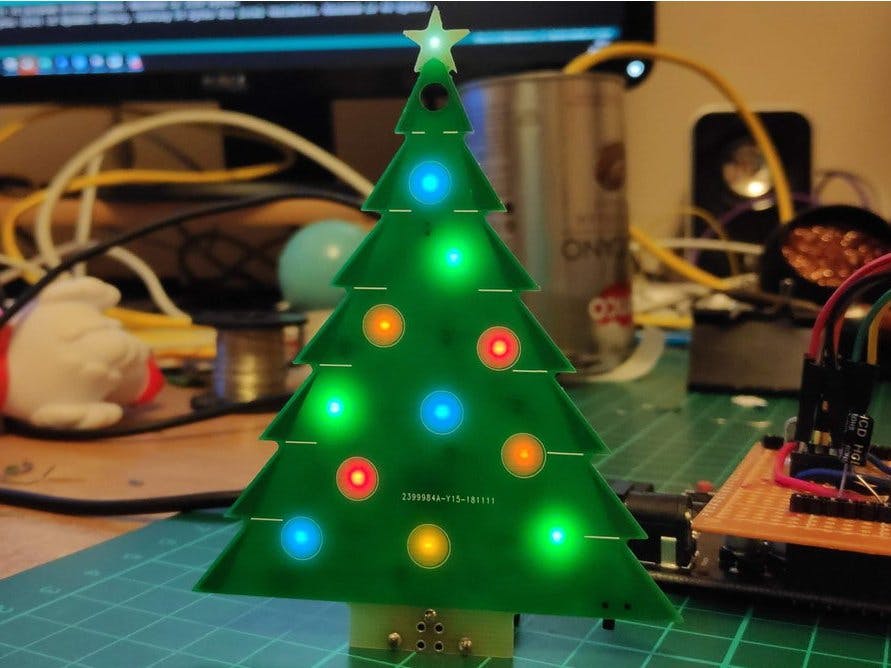
I have long been an admirer of the amazing things people were making as part of #badgelife and wanted to try replicating some of the features seen in them. I thought the baubles would be a perfect candidate for the LEDs being reverse mounted. I also thought it would make a really interesting tree ornament for our Christmas tree!
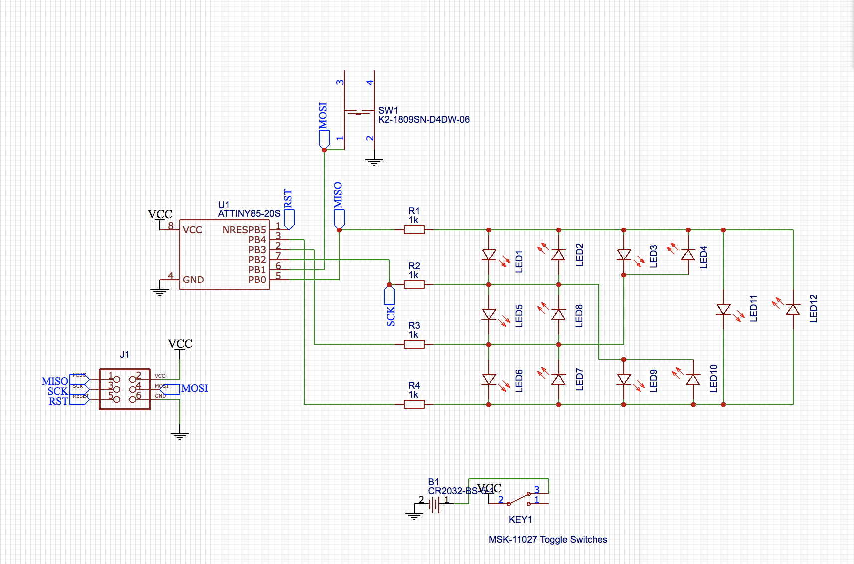
The tree has 12 LEDs that are reverse mounted to shine through the PCB that are controlled by an ATtiny13 (programmed using Arduino) and is powered using an CR2032 coin cell battery.
The PCB3 can be hung from a tree, can free stand (it uses the battery holder as a stand!) or can be used as an add on to a larger badge using the SAO connector.
I sell this as a kit on Tindie if you are interested in getting one!
- 12 reverse mounted LEDs
- You can select different modes for the LEDs using the built-in button. There is also a switch for turning off the power.
- It can be fully modified/hacked using the AVR ISP pins.
- Kickstand battery tab (This idea came from a viewer on one of my Live streams as I was creating to board!)
The tree has 12 different animation modes. To change the mode you press and hold the mode button til a single LED is lit up and continue to hold the button til the LED that corresponds to the mode you want is lit, then release.
The modes are as follows:
- 0 - Single Flash fastest
- 1 - Single Flash fast
- 2 - Single Flash
- 3 - Single Flash slow
- 4 - Single Flash slowest
- 5 - Dual Flash fastest
- 6 - Dual Flash fast
- 7 - Dual Flash
- 8 - Dual Flash slow
- 9 - Dual Flash slowest
- 10 - All LEDs on
- 11 - All LEDs blink
I designed the PCB in EasyEDA, which might not be the best choice for these style boards, but it is the one I am the most comfortable with. For the majority of it, its a pretty standard board, just with the board outline in the shape of a Christmas tree!
The different shading on the sides of the tree is achieved by adding a copper layer.The real star of the show, and the biggest challenge for me, is the reverse mounted LEDs.
This is achieved by not having any solder mask (the colour of a PCB which is often green or Oshpark has purple) or any copper so the LED can shine through and be diffused.
I just want caveat the below, this is all new to me so I'm not sure if this is the correct way to do it!
The first thing you need to do is add the Top & Bottom Solder Mask layer to the shown views, you do this by clicking on the cog on the layers window and adding the layers.
Almost counter intuitively, adding designs on these layers is the instruction to not add Solder mask to that area. For the LEDs I added a square to the bottom Solder Mask layer (the same side the LED is mounted), so there would be no solder mask between the pads of the LED and added a larger circle on the Front Solder Mask Layer. I guessed the size of the larger circle in terms of how much the LED will diffuse (it's about 0.7cm in diameter). The direction of the LED is normally indicated by some silkscreen (what gets printed to the PCB, text etc. It's normally white) in between the two pads, but since this needs to be clear I added an arrow to the outside to indicate polarity
You can buy specific reverse mount LEDs but I normally buy all the components for my projects from China and reverse mount LEDs don't seem to be too easy to come by. But I was speaking to Dave Darko and he was telling me he just used regular 0603 LEDs upside down in his word clock project.
Soldering them upside down is not as difficult as I initially thought it would be. This was my first time soldering 0603 parts and it wasn't too bad, the hardest part is actually keeping it flat to the board. For soldering, just put a bit more solder on the first pad than you would normally and place the LED carefully down with a tweezers.
BOM:- 1 PCB3
- 1 ATtiny13A-SS7
- 4 100 Ohm 0805 Resistors
- 12 0603 LEDs (1 white for the star, others a mix of colours)
- 1 Battery Holder
- 1 Toggle switch
- 1 Tactile button
I used LCSC to get all the parts for this project(other than the ATtiny13) (affiliate link)
Programming the ATtiny13:The ATtiny13 is an extremely cheap micrcontroller, its relatively limited in what you could use it for, but its perfect for a badge or something simple like the PCB3. You can pick them up for 25c each in quantities as little as 10 from Aliexpress (affiliate link).
I used the ATtiny85 programming shield I built in this guide to program the ATtiny13, you don't need to install the ATtiny stuff from that guide, but you do need the shield and to set-up the Uno or Mega to be an ISP programmer.
I also used an SMD socket board in the IC socket, these have a spring socket for holding the SMD chips in place. (Just a note, I needed to bend the header pins of the SMD socket board to fit into the IC socket as they were too wide to fit by default)
SMD Socket (Affiliate Link)
Install Micro core hardware package into the arduino IDE to enable compiling for the ATtiny13, follow the install instructions on the github page for the project.
The ATtiny can also be programmed after being installed to the tree using the build in ISP header pads.
One very interesting thing about working with the ATtiny13 is how little space there is on the chip! As someone who is used to writing C# and Javascript apps, 1024 KB is not a lot of space!
Using Dave Darko's sloth badge project as a base, I managed to add 12 different animation to the board that are controlled by the button on the back of the tree, but it was a tight squeeze! I don't think I had ever gotten the "not enough space" error when trying to upload before this project!
Dave had a lot of the work done, but some of the things you can do to save space is avoid some of the convenience methods provided by arduino such as DigitalWrite and set the registers manually (I definitely need to do some more reading up on this
If you have ever needed to program 50 of something, you will know you will do anything to save time! I ended up writing a batch file to help programming the ATtiny13 faster than I could with the Arduino IDE be calling the same AVRdude commands that were involved in burning the bootloader and uploading the sketch. The batch file performs the actions and then prompts to ask do you want to perform again, so after you swap the chip out you can kick off the upload again.
You can see what the arduino IDE is doing under the hood by enabling verbose output in the preferences menu.
Hopefully you found this interesting, If there is anything else you would like to ask or know, please let me know!


Comments
Please log in or sign up to comment.