


Hardware components | ||||||
| × | 1 | ||||
| × | 1 | ||||
| × | 1 | ||||
 |
| × | 1 | |||
 |
| × | 1 | |||
| × | 1 | ||||
 |
| × | 1 | |||
 |
| × | 1 | |||
| × | 2 | ||||
| × | 1 | ||||
 |
| × | 1 | |||
Software apps and online services | ||||||
 |
| |||||
| ||||||
| ||||||
I started this project because I want to be able to wirelessly measure AC power very easily. I'd like to clamp a current transformer on a wire, and start collecting readings right away on my LoraWAN network.
I'm inspired by how easy it is to use a battery powered meter, like this one.
The battery powered meter above only measures apparent amps, not real power, though. It is important to measure apparent power and real power, so I can calculate power factor. This means I need to measure a voltage signal, and detect the phase difference between the voltage and current signals. My goal is to use non-contact voltage sensing to do this.
I also want a sensor that I can clip on and leave forever, without worrying about the battery running out. In theory this should be possible too: a CT clamp will produce a current proportional to the current flow in the primary conductor, and I should be able to use this current to charge my battery.
Ideally it would look like this (below). This would be very easy to install. It will measure current flow, sense voltage, and charge itself.
Most power meters require three electrical connections: A current transformer to measure current, a connection to 120, 208, 240 or 480V AC to measure voltage and phase, and a third connection to power the device. All of this wiring is annoying and requires handling dangerous voltages.
Lets see if we can avoid all of this wiring, and build my ideal sensor.
Building the SensorThis LoraWAN AC Current sensor is made of 5 modules.
- HCT21 Current sensor module - an I2C 3 phase current sensor
- HCT10 CT Energy Harvest Module - to power the device
- Seeed Grove Wio E5 LoraWAN transceiver - controlled via UART
- Seeed Xiao ESP32C3 micropython MCU
- Seeed Grove Base for XIAO to tie everything together
This is what it looks like
Here is how the modules are wired together:
I like modular construction because you can re-use the modules at the end of the life of the sensor unit. At the end of (first) life you have valuable electronic modules - assets, not ewaste, which is just a liability. (See Modular LoraWAN end node)
HCT21 I2C AC Current sensorThis module uses an ATtiny3224 MCU to act as a smart I2C 12-bit differential ADC. The MCU is programmed to compute the RMS AC current. The ADC also samples a high impedance voltage signal, which allows for non-contact voltage sensing to compute the real and apparent AC current. Alternately, a 24VAC signal can be reduced with a resistor divider and connected to the voltage input, with the added benefit of measuring absolute voltage as well as phase.
The module is connected to 1, 2, or 3 current transformers to measure AC current. The transformers are 50A:50mA. Any CT that has a 50mA output can be used, for example 100A, 200A, 400A, or 600A.
More details are here.
This sensor module was part of my entry to the Seeed Grove sensor co-invent campaign, it's a great opportunity for anyone to make your dreamed sensor a reality.
This module bases on an ATtiny3224 could have up to 6 channels of voltage and current measurements, and a future module based on the sister chip ATtiny3226 could have up to 12 channels of voltage and current measuements.
HCT10 CT Energy HarvestEnergy harvesting from a CT can use a simple power supply circuit design. The CT will produce a 0-50mA AC current proportional to the current flowing through the primary conductor. As long as some current is flowing in the primary conductor, we can use this current to power our circuit.
The four diodes rectify this signal, the capacitor smooths the signal to reduce ripple, and the zener diode limits the highest voltage that the circuit can reach. The rectified DC is used to charge a Lithium 3.7v battery. The battery used must have a low-voltage cutout and high voltage cutout circuit, as this circuit does not otherwise prevent over- or under-charging. Vbat_sense is 1/4 of VBAT, and is used by the MCU to measure the battery voltage and calculate the state of charge. I found that when the primary conductor is carrying at least 10-15% of the CT's rated maximum current (CT secondary > 8mA), this circuit will charge the battery.
This module sits between the battery and the Grove Base. This module will charge the battery when excess CT current is available.
Seeed Grove Wio E5 LoraWAN transceiverThis module is an easy to use version of the STM32WLE5JC processor with a Lora module, built-in AT command firmware, and a Grove UART connector. For example you can send it an "AT+JOIN" command to join a LoraWAN network, and "AT+MSGHEX="1234" to send a LoraWAN message. While UART interfaces are a bit annoying to use, this still seems much easier that using a lower-level SPI module.
Seeed Xiao ESP32C3This module is the main MCU used to bring together the LoraWAN module and the I2C current sensor. As it has plenty of power, it can run MicroPython, which makes software development a lot easier. Furthermore, it will allow for WiFi communication and BLE configuration to be developed. This MCU can also sample temperature from one or more DS18B20 temperature sensors.
With sleeping, the unit averages 1mA of current when LoraWAN messages are sent every 3 minutes.
Seeed Grove BaseThe XIAO ESP32C3 plugs into the Grove Base and provides Grove connectors to hook up the the other modules.
Data Reception and DisplayA The Things Network (TTN) Indoor Gateway, RAK LPS8v2, or other LoraWAN gateway can receive the loraWAN signal form one or more sensors. A node-red installation copies the data to Influxdb, and Grafana can be used to visualize the data. In the case of the LPS8v2, all of these services can be run locally on the gateway. Or, with the TTN gateway, free SaaS TTN, InfluxDB, and Grafana instances can be used along with a self-hosted node-red.
The LoraWAN network has much lower bandwidth than WiFi, but uses a lot less power and has a much better noise margin. A LoraWAN signal can be received down to about -115 RSSI, compared to about -78 RSSI for WiFi. So it is possible to receive data from a sensor in a metal enclosure, or far away in an other building, with only one gateway per site.
At present this device is not perfect. I am using two CTs, one to power the device and one to measure current. And while the voltage sensing wire (a small coaxial cable) only needs to be placed near the primary conductor, and not connected to it, there is still another wire.
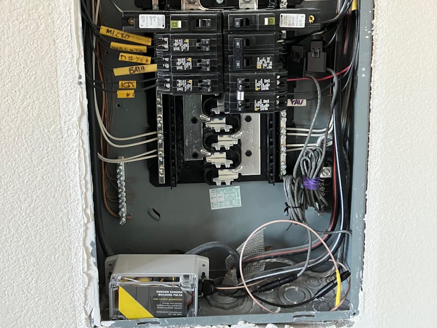
So I have this for the moment:
It measures the current flow using the black CT, and powers the device using the CT with the purple band. Voltage is sensed using the coaxial cable. I have partly achieved my goal - the device continuously recharges itself as long as at least 4A flows through the primary conductor, which induces an 8mA flow through the CT secondary.
I still need to improve this device to allow just one CT to power the device and measure the current, instead of two. And I need to find a nicer way to sense the non-contact voltage signal, perhaps binding both wires into one cable. Also it would be good to be able to energy harvest from the CT at lower current levels. Any suggestions you might have for these issues would be welcome. Please contact any of us if you would like to join our open source team buildingPULSE.


Comments
Please log in or sign up to comment.