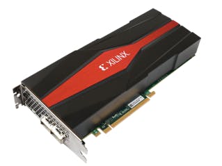
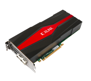
Aim of this project is to simulate a sample scenario of multiple users/mobile devices that are connected to a 5G Massive MIMO base station and estimate the direction of signal source via VCK5000 that runs Resnet50 CNN.
The project is composed of 2 main parts;
- Simulation of signals received by 5G Massive MIMO base station
- Estimating the direction of source signals by utilizing a Resnet50 CNN architecture on VCK5000 DPU
SIMULATION OF SOURCE SIGNALS
Incoming signals are simulated by PyLayers millimetre wave 5G ray tracing simulator which is capable of simulating ray characteristics of a radio signal in a sample area with buildings/obstacles. Incoming signals are simulated for a given transmitter position, base station position and sample environment by considering signal reflections caused by buildings. Figures below show reflections of an incoming signal simulated in a test area.
In the simulation, signals incoming to a 5G MIMO base station having 256 receive antenna elements are obtained with their time/phase characteristics. Signal sources frequency range is 24-25GHz and base station antenna elements are placed as 16x16 matrix with a spacing of half of the wavelength which is 6 mm. Since antenna elements are on different positions with respect to a signal source, incoming signals on different elements are expected to have a phase difference. Figures below show incoming signals on different antenna elements for 1 signal source.
As can be seen on figures above, incoming signals on the base station antenna element-1 and antenna element-2 have phase difference of 1.48 ( 2571.57 - 2570.09 ) time units.
If the signal source is located on a different position, phase characteristics of an incoming signal on a particular antenna element is expected to change. Figures below shows the change in incoming signal on antenna element-1 when the position of the signal source changes.
Comparing figure-2 and figure-5, phase difference of the incoming signal on antenna element-1 is obtained as 999.48 ( 2571.57 - 1572.09 ) time units.
From 1 to 100 signal sources having different locations can be simulated and incoming signals on each 256 antenna elements are obtained as amplitude vs time data with the amplitude scale of 0 to 1 and time scale of 0 to 10000 time units.
ESTIMATING DIRECTION OF SOURCE SIGNALS
To estimate the direction of signal sources Resnet50-149 layers CNN is deployed. CNN is trained with 192 antenna elements incoming signal data for 50 different locations of 1 signal source. Each incoming signal data contains 10000 signal amplitudes representing amplitude vs time data characteristics of the signal. Training labels include 50 different azimuth and elevation angles of signal source direction with respect to the base station. Training dataset includes 50x192 incoming signals data and evaluation dataset includes 50x64 incoming signals data. Input data of the CNN is represented as 100x100 data matrix which is basically shaped version of the incoming signal data. The CNN is trained for 200 epochs and the process is very similar to the Xilinx Vitis-AI tutorial in the url given below.
Trained CNN model is quantized and compiled for VCK5000-ES1 DPUCVDX8H which runs by host deployment software using Vitis AI Run time C++ framework. During the system test, input data for host deployment software is obtained from GUI/simulator software. Multiple signal source locations can be chosen with the GUI and simulator software calculates the superposed signal output. GUI can be seen on the figure below.
The system is composed of a host PC (Ubuntu 18.04) and VCK5000-es1 card installed into the PCIe slot.
The setup for the project is composed of 2 main parts;
- Setting up host application software
- Setting up the simulation software
APPLICATION SOFTWARE SETUP
To run the application software Vitis-AI 1.4.1 needs to be installed as described in;
https://github.com/Xilinx/Vitis-AI/tree/v1.4.1
and VCK5000-es1 setup process should be completed as described in;
https://github.com/Xilinx/Vitis-AI/tree/v1.4.1/setup/vck5000
Activate docker vitis-ai 1.4.1 and tensorflow2 conda environment.
Copy "5g_MIMO” folder supplied in the attachments to preferred location in PC.
SIMULATION SOFTWARE SETUP
Activate docker vitis-ai and tensorflow2 conda environment. Copy “pylayers” folder supplied in the attachments to "5g_MIMO” folder. Open “pylayers" folder and run "./installer_unix” file. This will install simulation software and required packages into the conda environment. After installation replace the folder created as “pylayers_project” with the “pylayers_project” folder supplied in the attachments.
Important Notes:
It is advised to use python 3.7.1 for the simulator and environment yml file is attached to install conda packages.
DEPLOYMENT INSTRUCTIONActivate docker vitis-ai and tensorflow2 conda environment.
Open "5g_MIMO” folder, run GUI with the command
python main.pyin the terminal and GUI will pop-up as shown in figure-6.
Choose source signal positions by clicking rectangle areas as shown in the figure below.
Click 'START SIMULATION' button and wait for ’Simulation Completed’ indicator.
Run the command
./resnet_example ./resnet50_tf2.xmodelIn the terminal an output is expected to be similar to given figure below.
In figure-9, “Azm” part shows azimuth angle, “Elv” part shows elevation angle in degrees.
To run simulation again click 'INITIALIZE SIMULATOR’ button and wait for ’System Initialized’ indicator.
New simulation can be started by choosing locations and clicking 'START SIMULATION’ button again.


Comments
Please log in or sign up to comment.