


Hardware components | ||||||
 |
| × | 1 | |||
 |
| × | 1 | |||
| × | 1 | ||||
| × | 1 | ||||
INTRODUCTION
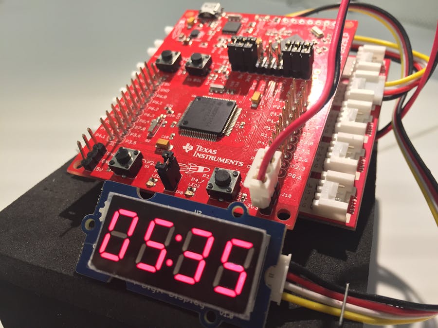
Welcome to the exciting world of the TI LaunchPad! Whether you are just getting started, or a master programmer, within minutes you will be making your own personal Alarm Clock. This guide will provide step by step instructions on installing required software, running the code and setting the clock. You will gain some great experience using the Energia IDE and the LaunchPad ecosystem.
HARDWARE
Today we will be using the following components to build the Alarm Clock:
- MSP430F5529 LaunchPad
- SeeedStudio Grove 4-Digit Display
- SeeedStudio Grove Buzzer
Now that we have all of our components, lets put them together! Energia makes things easy by providing a pin mapping guide for all of the LaunchPads and BoosterPacks supported.
For this project we have the Buzzer connected to Pin 39 on the LaunchPad and the 4-Digit Display (Clock to Pin 9 & DIO to Pin 10). Once you have done this you are ready to install some software!
SOFTWARE
Before we can start having fun, we need to prepare your system with the necessary software, drivers and tools in order to have a successful project. The Energia IDE not only allows us to write and debug our program, but provides the ability to export the code to most of LaunchPads currently available.
Let’s start out by downloading the latest version of Energia by visiting energia.nu/download and downloading the correct version for your operating system.
In order to use Energia you will need to have the LaunchPad drivers installed. The drivers allow your machine to “see” the LaunchPad on a serial COM port when it is connected. In this example we will be using the MSP430F5529 LaunchPad therefore it is necessary to follow the instructions related to your operating system. Download the drivers using the following links:
Now that you have your programming environment installed and ready to go, it's time to download the code. The main code for the alarm clock and all of the libraries needed have been provided in the sections below. You should have all of the .cpp files and the .h files saved within your library folder of Energia, usually found in Users/Documents/Energia/libraries. Now you can begin a new project and copy an paste the Main Alarm Code into your project.
Untitled file
Warning: Embedding code files within the project story has been deprecated. To edit this file or add more files, go to the "Software" tab. To remove this file from the story, click on it to trigger the context menu, then click the trash can button (this won't delete it from the "Software" tab).
#include "sRTCsec.h";
#include "legacymsp430.h"
#include "TimerSerial.h"
#include "ClickButton.h"
#include "TM1637.h"

#define CLK 9//pins definitions for TM1637 and can be changed to other ports
#define DIO 10

#define BUZZER_PIN               39            /* sig pin of the buzzer */
TM1637 tm1637(CLK,DIO);

#define OFF 0
#define ON 1

int8_t TimeDisp[] = {
  0x00,0x00,0x00,0x00};

int8_t RealTimeDisp[] = {
  0x00,0x00,0x00,0x00};
unsigned char ClockPoint = 1;
unsigned char Update;

// Declaring the constant values that will not change

const int  buttonPin1 = PUSH1;    // the pin that the pushbutton is attached to
ClickButton button1(buttonPin1, LOW, CLICKBTN_PULLUP);

const int  buttonPin2 = PUSH2;    // the pin that the pushbutton is attached to
ClickButton button2(buttonPin2, LOW, CLICKBTN_PULLUP);

const int ledPin1 = RED_LED;       // the pin that the LED is attached to
const int ledPin2 = GREEN_LED;      // the pin that the LED is attached to

TimerSerial mySerial;
RealTimeClockSec myRTC;

int ledState = LOW;

// Declaring the variables that will change:

// Referring to PUSH 1
int buttonPushCounter1 = 0;   // counter for the number of button presses
int buttonState1 = 0;         // current state of the button
int lastButtonState1 = 0;     // previous state of the button

// Referring to PUSH 2
int buttonPushCounter2 = 0;   // counter for the number of button presses
int buttonState2 = 0;         // current state of the button
int lastButtonState2 = 0;     // previous state of the button

int hrsSet =  0;              // keeps track of the actual time hour set
int minSet =  0;              // keeps track of the actual time minute set
int alarmHrs = 0;             // keeps track of the alarm time hour set
int alarmMin = 0;             // keeps track of the alarm time minute set
int alarmSec = 0;             // keeps track of the alarm time second set

// Various flags used  throughout the timeset and alarmset functions:
int hrflag = 0;               // keeps track of time set toggle for hours
int minflag = 0;              // keeps track of time set toggle for minutes
int firstTime = 1;
int clicksflag = -1;
int stateflag = 0;
int alarmflag  = 0; // keeps track of alarm on/off 0 = off


// ButtonClicks1 function calculates the number of times Push 1 has been pressed
void ButtonClicks1(void) {
  // read the pushbutton input pin:
  buttonState1 = !digitalRead(buttonPin1);

  // compare the buttonState to its previous state
  if (buttonState1 != lastButtonState1) {
    // if the state has changed, increment the counter
    if (buttonState1 == HIGH) {
      // if the current state is HIGH then the button
      // wend from off to on:
      buttonPushCounter1++;
      Serial.println("on");
      Serial.print("number of button 1 pushes:  ");
      Serial.println(buttonPushCounter1);
    }
    else {
      // if the current state is LOW then the button
      // wend from on to off:
      Serial.println("off");
    }
  }
  // save the current state as the last state,
  //for next time through the loop
  lastButtonState1 = buttonState1;
}


// ButtonClicks2 function calculates the number of times Push 2 has been pressed
void ButtonClicks2(void) {
  // read the pushbutton input pin:
  buttonState2 = !digitalRead(buttonPin2);

  // compare the buttonState to its previous state
  if (buttonState2 != lastButtonState2) {
    // if the state has changed, increment the counter
    if (buttonState2 == HIGH) {
      // if the current state is HIGH then the button
      // wend from off to on:
      buttonPushCounter2++;
      Serial.println("on");
      Serial.print("number of button 2 pushes:  ");
      Serial.println(buttonPushCounter2);
    }
    else {
      // if the current state is LOW then the button
      // wend from on to off:
      Serial.println("off");
    }
  }
  // save the current state as the last state,
  //for next time through the loop
  lastButtonState2 = buttonState2;

}


// TimeUpdate allows the user to set the actual time and places the values set into RTC
// Time is displayed in 4-Digit display

void TimeUpdate(void)
{
  if(ClockPoint)tm1637.point(POINT_ON);    // Turns
  else tm1637.point(POINT_OFF);

   while(1){
   button1.Update();
   ButtonClicks1();
   ButtonClicks2();
  if ((buttonPushCounter1 % 2) == 0)      // Editing the hour side HH:MM = H1 H2 :M1 M2
  {
Serial.println("TIME UPDATE MODE we are changing hours");
    if(hrflag == 0){
      hrflag = 1;
      minflag = 0;

      if(firstTime){
        minSet = 0;
        firstTime = 0;
      }
      else
        minSet = buttonPushCounter2;

      buttonPushCounter2 = hrsSet;
    }

    hrsSet = (buttonPushCounter2 % 24);

    TimeDisp[0] = (hrsSet/10)%10;
    TimeDisp[1] = (hrsSet%10)%10;

  }
  else if ((buttonPushCounter1 % 2) == 1)
  {
    Serial.println("TIME UPDATE MODE we are changing mins");
     if(minflag == 0){
      hrflag = 0;
      minflag = 1;
      hrsSet = buttonPushCounter2;
      buttonPushCounter2 = minSet;
    }

    minSet = (buttonPushCounter2 % 60);

    TimeDisp[2] = (minSet /10)%10;
    TimeDisp[3] = (minSet %10)%10;

  }

  button1.Update();
  tm1637.display(TimeDisp);


    if(button1.clicks ==2){    // Exit Time Update mode when double clicking

    myRTC.RTC_hr = hrsSet % 24;
    myRTC.RTC_min = minSet % 60;
    myRTC.RTC_sec = 0;
    stateflag = 0;
    return;
   }
   }
  Update = OFF;
};


// AlarmSet function allows user to set an alarm time and stores values
// Alarm time is displayed in 4-Digit display

void AlarmSet(void)
{

  if(ClockPoint)tm1637.point(POINT_ON);
  else tm1637.point(POINT_OFF);

   while(1){
   button1.Update();
   ButtonClicks1();
   ButtonClicks2();
  if ((buttonPushCounter1 % 2) == 0)
  {
Serial.println("ALARM SET MODE we are changing hours");
    if(hrflag == 0){
      hrflag = 1;
      minflag = 0;

      if(firstTime){
        minSet = 0;
        firstTime = 0;
      }
      else
        minSet = buttonPushCounter2;

      buttonPushCounter2 = hrsSet;
    }

    hrsSet = (buttonPushCounter2 % 24);

    TimeDisp[0] = (hrsSet/10)%10;
    TimeDisp[1] = (hrsSet%10)%10;

  }
  else if ((buttonPushCounter1 % 2) == 1)
  {
    Serial.println("ALARM SET MODE we are changing mins");
     if(minflag == 0){
      hrflag = 0;
      minflag = 1;
      hrsSet = buttonPushCounter2;
      buttonPushCounter2 = minSet;
    }

    minSet = (buttonPushCounter2 % 60);

    TimeDisp[2] = (minSet /10)%10;
    TimeDisp[3] = (minSet %10)%10;
  }


  button1.Update();
  tm1637.display(TimeDisp);

    alarmHrs = hrsSet % 24;
    alarmMin = minSet % 60;

    if(button1.clicks ==2){    // Exit Alarm Set mode when double clicking
    stateflag = 0;
    Serial.print("Alarm Time Set:");
    Serial.print(alarmHrs);
    Serial.print(":");
    Serial.print(alarmMin);
    return;
   }
   }
  Update = OFF;
};


// AlarmOn checks if all criteria is met to turn on the Alarm
void AlarmOn(void)
{
  // If the alarm is on and the alarm time set matches the current time
  if ((alarmflag == 1) && (alarmHrs == myRTC.RTC_hr) && (alarmMin == myRTC.RTC_min) && (alarmSec == myRTC.RTC_sec))
    {
    digitalWrite(ledPin2, HIGH);       // turn the Green LED on while alarm goes off
    Serial.println("Alarm IS ON!!");   // Prints to Serial Monitor (Alarm is on)
    digitalWrite(BUZZER_PIN,HIGH);

    }
    else if (digitalRead(PUSH2) == LOW) {
    digitalWrite(ledPin2, LOW);   // turn the Green LED off while alarm goes off
    digitalWrite(BUZZER_PIN,LOW);
    return;
    }
}


// Debug Function - Allows user to view the current time,
void Debug (void)
{
    Serial.print(myRTC.RTC_hr, DEC);
    Serial.print(":");
    Serial.print(myRTC.RTC_min, DEC);
    Serial.print(":");
    Serial.print(myRTC.RTC_sec, DEC);
    Serial.print("   Alarm Flag: ");
    Serial.print(alarmflag);
    Serial.print("   Alarm Set Time ");
    Serial.print(alarmHrs);
    Serial.print(":");
    Serial.println(alarmMin);

}

// QuickBeep funtion makes the buzzer beep once for 200ms
void QuickBeep(void){
  digitalWrite(BUZZER_PIN,HIGH);
  delay(200);
  digitalWrite(BUZZER_PIN,LOW);
}

// QuickBeeps funtion makes the buzzer beep twice for 200ms with 100ms delay in between
void QuickBeeps(void){
  digitalWrite(BUZZER_PIN,HIGH);
  delay(200);
  digitalWrite(BUZZER_PIN,LOW);
  delay(100);
  digitalWrite(BUZZER_PIN,HIGH);
  delay(200);
  digitalWrite(BUZZER_PIN,LOW);
}
void fin() {
  Serial.end();
};


// Setup function runs once at the start

void setup() {
  // initialize the button pin as a input:
  pinMode(buttonPin1, INPUT_PULLUP);
  pinMode(buttonPin2, INPUT_PULLUP);
  // initialize the LED as an output:
  pinMode(ledPin1, OUTPUT);
  pinMode(ledPin2, OUTPUT);
  pinMode(BUZZER_PIN, OUTPUT);
  digitalWrite(BUZZER_PIN,LOW);
  pinMode(2, OUTPUT);

  // This is to close the serial output so you are able to upload a new sketch to the LaunchPad
  pinMode(5, INPUT_PULLUP),
  attachInterrupt(5,fin,LOW);

  // initialize serial communication:
  Serial.begin(9600);

  // Adjusting the timer preferences
  tm1637.init();
  tm1637.set(BRIGHT_TYPICAL);//BRIGHT_TYPICAL = 2,BRIGHT_DARKEST = 0,BRIGHTEST = 7;

  button1.debounceTime   = 20;   // Debounce timer in ms
  button1.multiclickTime = 250;  // Time limit for multi clicks
  button1.longClickTime  = 1000; // time until "held-down clicks" register
}


void loop() {

  button1.Update();

  ButtonClicks1();
  ButtonClicks2();


switch (stateflag){ //Toggle between the different modes

  case 2:    // TIME UPDATE MODE

    Serial.println("ENTERED TIME UPDATE MODE");
    digitalWrite(ledPin2, HIGH);   // turn the Green LED while time is being set
    TimeUpdate();                  // Calls the TimeUpdate function
    tm1637.display(TimeDisp);      // Displays the time on LCD
    digitalWrite(ledPin2, LOW);    // turn the green LED off
    Serial.println("EXIT TIME UPDATE MODE");
    QuickBeeps();

    break;

  case 3:    // ALARM SET MODE

    Serial.println("ENTERED ALARM SET MODE");
    digitalWrite(ledPin1, HIGH);   // turn the Red LED while alarm time is being set
    AlarmSet();                    // Calls the AlarmSet funtion
    tm1637.display(TimeDisp);      // Displays time on LCD
    digitalWrite(ledPin1, LOW);    // turn the red LED off
    Serial.println("EXIT ALARM SET MODE");
    QuickBeeps();
    break;

  case 0:    // Default mode where time is displayed once it has been set

    Serial.println("TIME DISPLAY MODE");

    while(1) {
    AlarmOn();
    RealTimeDisp[0] = (myRTC.RTC_hr / 10);
    RealTimeDisp[1] = (myRTC.RTC_hr % 10);
    RealTimeDisp[2] = (myRTC.RTC_min / 10);
    RealTimeDisp[3] = (myRTC.RTC_min % 10);
    tm1637.display(RealTimeDisp);

    if ((myRTC.RTC_sec % 2)==0 && ledState== LOW) {
      ledState = HIGH;
     Debug();
    };

    if ((myRTC.RTC_sec % 2)==1 && ledState== HIGH) {
      ledState = LOW;
     Debug();

   };


  ButtonClicks2();

  // Turning the Alarm On or Off pressing Push 2 while in Default Mode
   if ((buttonPushCounter2 % 2) == 0) {
      digitalWrite(ledPin1, LOW);   // turn the Red LED to display ALARM is ON
      alarmflag = 0;

    }
    else if ((buttonPushCounter2 % 2) == 1) {
     digitalWrite(ledPin1, HIGH);   // turn the Red LED to display ALARM is ON
     alarmflag = 1;

  }
    button1.Update();

    if (button1.clicks == 2){
      stateflag = 2;


      QuickBeeps();
      break;
    }
    if (button1.clicks == 3){
      stateflag = 3;
      QuickBeeps();
      break;
    }
    }
    break;
}

};


interrupt(TIMER1_A0_VECTOR) Tic_Tac(void) {
  myRTC.Inc_sec();              // Update seconds
};
The Following Library files should be placed in the appropriate folder :
- ClickButton.cpp
- ClickButton.cpp
- ClickButton.h
- sRTCsec.cpp
- sRTCsec.h
- TM1637.cpp
- TM1637.h
Untitled file
Warning: Embedding code files within the project story has been deprecated. To edit this file or add more files, go to the "Software" tab. To remove this file from the story, click on it to trigger the context menu, then click the trash can button (this won't delete it from the "Software" tab).
/*    ClickButton

 Arduino library that decodes multiple clicks on one button.
 Also copes with long clicks and click-and-hold.

 Usage: ClickButton buttonObject(pin [LOW/HIGH, [CLICKBTN_PULLUP]]);

  where LOW/HIGH denotes active LOW or HIGH button (default is LOW)
  CLICKBTN_PULLUP is only possible with active low buttons.


 Returned click counts:

   A positive number denotes the number of (short) clicks after a released button
   A negative number denotes the number of "long" clicks

NOTE!
 This is the OPPOSITE/negative of click codes from the last pre-2013 versions!
 (this seemed more logical and simpler, so I finally changed it)

 Based on the Debounce example at arduino playground site


 Copyright (C) 2010,2012, 2013 raron


 GNU GPLv3 license

 This program is free software: you can redistribute it and/or modify
 it under the terms of the GNU General Public License as published by
 the Free Software Foundation, either version 3 of the License, or
 (at your option) any later version.

 This program is distributed in the hope that it will be useful,
 but WITHOUT ANY WARRANTY; without even the implied warranty of
 MERCHANTABILITY or FITNESS FOR A PARTICULAR PURPOSE.  See the
 GNU General Public License for more details.

 You should have received a copy of the GNU General Public License
 along with this program.  If not, see <http://www.gnu.org/licenses/>.


 Contact: raronzen@gmail.com


 History:
 2013.08.29 - Some small clean-up of code, more sensible variable names etc.
                Added another example code for multiple buttons in an object array
 2013.04.23 - A "minor" debugging: active-high buttons now work (wops)!
                Thanks goes to John F. H. for pointing that out!
 2013.02.17 - Some improvements, simplified click codes.
				Added a LED fader example. Thanks to Tom K. for the idea.
 2012.01.31 - Tiny update for Arduino 1.0
 2010.06.15 - First version. Basically just a small OOP programming exercise.
*/

#include "ClickButton.h"

ClickButton::ClickButton(uint8_t buttonPin)
{
  _pin           = buttonPin;
  _activeHigh    = LOW;           // Assume active-low button
  _btnState      = !_activeHigh;  // initial button state in active-high logic
  _lastState     = _btnState;
  _clickCount    = 0;
  clicks         = 0;
  depressed      = false;
  _lastBounceTime= 0;
  debounceTime   = 20;            // Debounce timer in ms
  multiclickTime = 250;           // Time limit for multi clicks
  longClickTime  = 1000;          // time until long clicks register
  pinMode(_pin, INPUT_PULLUP);
}


ClickButton::ClickButton(uint8_t buttonPin, boolean activeType)
{
  _pin           = buttonPin;
  _activeHigh    = activeType;
  _btnState      = !_activeHigh;  // initial button state in active-high logic
  _lastState     = _btnState;
  _clickCount    = 0;
  clicks         = 0;
  depressed      = 0;
  _lastBounceTime= 0;
  debounceTime   = 20;            // Debounce timer in ms
  multiclickTime = 250;           // Time limit for multi clicks
  longClickTime  = 1000;          // time until long clicks register
  pinMode(_pin, INPUT_PULLUP);
}

ClickButton::ClickButton(uint8_t buttonPin, boolean activeType, boolean internalPullup)
{
  _pin           = buttonPin;
  _activeHigh    = activeType;
  _btnState      = !_activeHigh;  // initial button state in active-high logic
  _lastState     = _btnState;
  _clickCount    = 0;
  clicks         = 0;
  depressed      = 0;
  _lastBounceTime= 0;
  debounceTime   = 20;            // Debounce timer in ms
  multiclickTime = 250;           // Time limit for multi clicks
  longClickTime  = 1000;          // time until "long" click register
  pinMode(_pin, INPUT_PULLUP);
  // Turn on internal pullup resistor if applicable
  if (_activeHigh == LOW && internalPullup == CLICKBTN_PULLUP) digitalWrite(_pin,HIGH);
}


void ClickButton::Update()
{
  long now = (long)millis();      // get current time
  _btnState = digitalRead(_pin);  // current appearant button state

  // Make the button logic active-high in code
  if (!_activeHigh) _btnState = !_btnState;

  // If the switch changed, due to noise or a button press, reset the debounce timer
  if (_btnState != _lastState) _lastBounceTime = now;


  // debounce the button (Check if a stable, changed state has occured)
  if (now - _lastBounceTime > debounceTime && _btnState != depressed)
  {
    depressed = _btnState;
    if (depressed) _clickCount++;
  }

  // If the button released state is stable, report nr of clicks and start new cycle
  if (!depressed && (now - _lastBounceTime) > multiclickTime)
  {
    // positive count for released buttons
    clicks = _clickCount;
    _clickCount = 0;
  }

  // Check for "long click"
  if (depressed && (now - _lastBounceTime > longClickTime))
  {
    // negative count for long clicks
    clicks = 0 - _clickCount;
    _clickCount = 0;
  }

  _lastState = _btnState;
}
Untitled file
Warning: Embedding code files within the project story has been deprecated. To edit this file or add more files, go to the "Software" tab. To remove this file from the story, click on it to trigger the context menu, then click the trash can button (this won't delete it from the "Software" tab).
#ifndef ClickButton_H

#define ClickButton_H


#if (ARDUINO <  100)

#include <WProgram.h>

#else

#include <Arduino.h>

#endif


#define CLICKBTN_PULLUP HIGH


class ClickButton

{

  public:

    ClickButton(uint8_t buttonPin);

    ClickButton(uint8_t buttonPin, boolean active);

    ClickButton(uint8_t buttonPin, boolean active, boolean internalPullup);

    void Update();

    int clicks;                   // button click counts to return

    boolean depressed;            // the currently debounced button (press) state (presumably it is not sad :)

    long debounceTime;

    long multiclickTime;

    long longClickTime;

  private:

    uint8_t _pin;                 // Arduino pin connected to the button

    boolean _activeHigh;          // Type of button: Active-low = 0 or active-high = 1

    boolean _btnState;            // Current appearant button state

    boolean _lastState;           // previous button reading

    int _clickCount;              // Number of button clicks within multiclickTime milliseconds

    long _lastBounceTime;         // the last time the button input pin was toggled, due to noise or a press

};


#endif
Untitled file
Warning: Embedding code files within the project story has been deprecated. To edit this file or add more files, go to the "Software" tab. To remove this file from the story, click on it to trigger the context menu, then click the trash can button (this won't delete it from the "Software" tab).
/*

 sRTC.h - Library for adding simple RTC capabilities using MSP430 hardware

 By Yannick DEVOS (XV4Y) - 2012

 */


// include this library's description file

#include <sRTCsec.h>

#include <legacymsp430.h>


// Constructor /////////////////////////////////////////////////////////////////


RealTimeClockSec::RealTimeClockSec(void)

{

    RTC_sec = 0;

    RTC_min = 0;

    RTC_hr = 0;


    WDTCTL = WDTPW | WDTHOLD; // Kill watch-dog


    UCSCTL1 = DIVA_3;        // Clock = ACLK / 8

    UCSCTL3 |= (XT1BYPASS | XCAP_3);        // Internal 12.5pF cap for 32KHz crystal


    TA1CCTL0 = CCIE;             //  CCR0 interupt activated

    TA1CCR0 = 4096-1;               // 4096 ticks of 32KHz XTal = 1 second => CCR0 counts N+1

    TA1CTL = TASSEL_1 | ID_3 | MC_1;  // Clock for TIMER 1 = ACLK, By 8 division, up front


};


// Methods /////////////////////////////////////////////////////////////////


void RealTimeClockSec::Inc_sec(void) {

    RTC_sec = RTC_sec + 1;            // Update seconds

    if (RTC_sec == 60) {

        RTC_sec=0;

        Inc_min();

    };

};


void RealTimeClockSec::Inc_min(void) {

    RTC_min = RTC_min + 1;            // Update minutes

    if (RTC_min == 60) {

        RTC_min=0;

        Inc_hr();

    };

};


void RealTimeClockSec::Inc_hr(void) {

    RTC_hr = RTC_hr + 1;              // Update hours

    if (RTC_hr == 24) {

        RTC_hr=0;

    };

};


void RealTimeClockSec::Set_Time(char hrs=0, char mins=0, char secs=0) {

    if ((hrs>=0 && hrs <24) && (mins>=0 && mins<60) && (secs>=0 && secs<60)) {

        RTC_hr = hrs;   // Set time to values given in parameters

        RTC_min = mins;

        RTC_sec = secs;

    };

};
Untitled file
Warning: Embedding code files within the project story has been deprecated. To edit this file or add more files, go to the "Software" tab. To remove this file from the story, click on it to trigger the context menu, then click the trash can button (this won't delete it from the "Software" tab).
/*

 sRTC.h - Library for adding simple RTC capabilities using MSP430 hardware

 By Yannick DEVOS (XV4Y) - 2012


///////////////////////////////// How to use the lib


 * Create an instance of the object


 RealTimeClock myClock;


 * In order to have this RTC library working you should add this code to the end of your main program :


 interrupt(TIMER1_A0_VECTOR) Tic_Tac(void) {

    myClock.Inc_sec();            // Update secondes

 };


 * Enjoy the clock reading the RTC_sec, RTC_min, RTC_hr variables


 */


// ensure this library description is only included once

#ifndef RTCsec_h

#define RTCsec_h


// library interface description

class RealTimeClockSec

{

    // user-accessible "public" interface

public:

    RealTimeClockSec(void);

    void Set_Time(char hr, char mins, char secs);

    char RTC_sec; // This how you read the time, by reading the vars

    char RTC_min;

    char RTC_hr;

    void Inc_sec(void); // This methode should be invoked by an Interrupt call (see top of the file comment)

    // A few private methods

private:

    void Inc_min(void);

    void Inc_hr(void);

};


#endif
Untitled file
Warning: Embedding code files within the project story has been deprecated. To edit this file or add more files, go to the "Software" tab. To remove this file from the story, click on it to trigger the context menu, then click the trash can button (this won't delete it from the "Software" tab).
//  Author:Frankie.Chu

//  Date:9 April,2012

//

//  This library is free software; you can redistribute it and/or

//  modify it under the terms of the GNU Lesser General Public

//  License as published by the Free Software Foundation; either

//  version 2.1 of the License, or (at your option) any later version.

//

//  This library is distributed in the hope that it will be useful,

//  but WITHOUT ANY WARRANTY; without even the implied warranty of

//  MERCHANTABILITY or FITNESS FOR A PARTICULAR PURPOSE.  See the GNU

//  Lesser General Public License for more details.

//

//  You should have received a copy of the GNU Lesser General Public

//  License along with this library; if not, write to the Free Software

//  Foundation, Inc., 51 Franklin St, Fifth Floor, Boston, MA  02110-1301  USA

//

//  Modified record:

//

/*******************************************************************************/


#ifndef TM1637_h

#define TM1637_h

#include <inttypes.h>

#include <Arduino.h>

//************definitions for TM1637*********************

#define ADDR_AUTO  0x40

#define ADDR_FIXED 0x44


#define STARTADDR  0xc0

/**** definitions for the clock point of the digit tube *******/

#define POINT_ON   1

#define POINT_OFF  0

/**************definitions for brightness***********************/

#define  BRIGHT_DARKEST 0

#define  BRIGHT_TYPICAL 2

#define  BRIGHTEST      7


class TM1637

{

  public:

    uint8_t Cmd_SetData;

    uint8_t Cmd_SetAddr;

    uint8_t Cmd_DispCtrl;

    boolean _PointFlag;     //_PointFlag=1:the clock point on

    TM1637(uint8_t, uint8_t);

    void init(void);        //To clear the display

    void writeByte(int8_t wr_data);//write 8bit data to tm1637

    void start(void);//send start bits

    void stop(void); //send stop bits

    void display(int8_t DispData[]);

    void display(uint8_t BitAddr,int8_t DispData);

    void clearDisplay(void);

    void set(uint8_t = BRIGHT_TYPICAL,uint8_t = 0x40,uint8_t = 0xc0);//To take effect the next time it displays.

    void point(boolean PointFlag);//whether to light the clock point ":".To take effect the next time it displays.

    void coding(int8_t DispData[]);

    int8_t coding(int8_t DispData);

  private:

    uint8_t Clkpin;

    uint8_t Datapin;

};

#endif
Untitled file
Warning: Embedding code files within the project story has been deprecated. To edit this file or add more files, go to the "Software" tab. To remove this file from the story, click on it to trigger the context menu, then click the trash can button (this won't delete it from the "Software" tab).
//  Author:Frankie.Chu

//  Date:9 April,2012

//

//  This library is free software; you can redistribute it and/or

//  modify it under the terms of the GNU Lesser General Public

//  License as published by the Free Software Foundation; either

//  version 2.1 of the License, or (at your option) any later version.

//

//  This library is distributed in the hope that it will be useful,

//  but WITHOUT ANY WARRANTY; without even the implied warranty of

//  MERCHANTABILITY or FITNESS FOR A PARTICULAR PURPOSE.  See the GNU

//  Lesser General Public License for more details.

//

//  You should have received a copy of the GNU Lesser General Public

//  License along with this library; if not, write to the Free Software

//  Foundation, Inc., 51 Franklin St, Fifth Floor, Boston, MA  02110-1301  USA

//

//  Modified record:

//

/*******************************************************************************/

#include "TM1637.h"

#include <Arduino.h>

static int8_t TubeTab[] = {0x3f,0x06,0x5b,0x4f,

                           0x66,0x6d,0x7d,0x07,

                           0x7f,0x6f,0x77,0x7c,

                           0x39,0x5e,0x79,0x71};//0~9,A,b,C,d,E,F

TM1637::TM1637(uint8_t Clk, uint8_t Data)

{

  Clkpin = Clk;

  Datapin = Data;

  pinMode(Clkpin,OUTPUT);

  pinMode(Datapin,OUTPUT);

}


void TM1637::init(void)

{

  clearDisplay();

}


void TM1637::writeByte(int8_t wr_data)

{

  uint8_t i,count1;

  for(i=0;i<8;i++)        //sent 8bit data

  {

    digitalWrite(Clkpin,LOW);

    if(wr_data & 0x01)digitalWrite(Datapin,HIGH);//LSB first

    else digitalWrite(Datapin,LOW);

    wr_data >>= 1;

    digitalWrite(Clkpin,HIGH);


  }

  digitalWrite(Clkpin,LOW); //wait for the ACK

  digitalWrite(Datapin,HIGH);

  digitalWrite(Clkpin,HIGH);

  pinMode(Datapin,INPUT);

  while(digitalRead(Datapin))

  {

    count1 +=1;

    if(count1 == 200)//

    {

     pinMode(Datapin,OUTPUT);

     digitalWrite(Datapin,LOW);

     count1 =0;

    }

    pinMode(Datapin,INPUT);

  }

  pinMode(Datapin,OUTPUT);


}

//send start signal to TM1637

void TM1637::start(void)

{

  digitalWrite(Clkpin,HIGH);//send start signal to TM1637

  digitalWrite(Datapin,HIGH);

  digitalWrite(Datapin,LOW);

  digitalWrite(Clkpin,LOW);

}

//End of transmission

void TM1637::stop(void)

{

  digitalWrite(Clkpin,LOW);

  digitalWrite(Datapin,LOW);

  digitalWrite(Clkpin,HIGH);

  digitalWrite(Datapin,HIGH);

}

//display function.Write to full-screen.

void TM1637::display(int8_t DispData[])

{

  int8_t SegData[4];

  uint8_t i;

  for(i = 0;i < 4;i ++)

  {

    SegData[i] = DispData[i];

  }

  coding(SegData);

  start();          //start signal sent to TM1637 from MCU

  writeByte(ADDR_AUTO);//

  stop();           //

  start();          //

  writeByte(Cmd_SetAddr);//

  for(i=0;i < 4;i ++)

  {

    writeByte(SegData[i]);        //

  }

  stop();           //

  start();          //

  writeByte(Cmd_DispCtrl);//

  stop();           //

}

//******************************************

void TM1637::display(uint8_t BitAddr,int8_t DispData)

{

  int8_t SegData;

  SegData = coding(DispData);

  start();          //start signal sent to TM1637 from MCU

  writeByte(ADDR_FIXED);//

  stop();           //

  start();          //

  writeByte(BitAddr|0xc0);//

  writeByte(SegData);//

  stop();            //

  start();          //

  writeByte(Cmd_DispCtrl);//

  stop();           //

}


void TM1637::clearDisplay(void)

{

  display(0x00,0x7f);

  display(0x01,0x7f);

  display(0x02,0x7f);

  display(0x03,0x7f);

}

//To take effect the next time it displays.

void TM1637::set(uint8_t brightness,uint8_t SetData,uint8_t SetAddr)

{

  Cmd_SetData = SetData;

  Cmd_SetAddr = SetAddr;

  Cmd_DispCtrl = 0x88 + brightness;//Set the brightness and it takes effect the next time it displays.

}


//Whether to light the clock point ":".

//To take effect the next time it displays.

void TM1637::point(boolean PointFlag)

{

  _PointFlag = PointFlag;

}

void TM1637::coding(int8_t DispData[])

{

  uint8_t PointData;

  if(_PointFlag == POINT_ON)PointData = 0x80;

  else PointData = 0;

  for(uint8_t i = 0;i < 4;i ++)

  {

    if(DispData[i] == 0x7f)DispData[i] = 0x00;

    else DispData[i] = TubeTab[DispData[i]] + PointData;

  }

}

int8_t TM1637::coding(int8_t DispData)

{

  uint8_t PointData;

  if(_PointFlag == POINT_ON)PointData = 0x80;

  else PointData = 0;

  if(DispData == 0x7f) DispData = 0x00 + PointData;//The bit digital tube off

  else DispData = TubeTab[DispData] + PointData;

  return DispData;

}
Setting the Clock
Now that you have all of your components in place, your code is working and you have uploaded it to your LaunchPad, it's time to set your clock! When you first load the program, you will notice that the time display will show 00:00. There are multiple modes which can be entered depending on the number of times you press the corresponding button. Below you will find a diagram which will help guide you through the different states of the the program.
Nice Work!! You now have a fully functional Alarm Clock!
Thanks for following this guide!
alarm_clock.ino
C/C++#include "sRTCsec.h";
#include "legacymsp430.h"
#include "TimerSerial.h"
#include "ClickButton.h"
#include "TM1637.h"
#define CLK 9//pins definitions for TM1637 and can be changed to other ports
#define DIO 10
#define BUZZER_PIN 39 /* sig pin of the buzzer */
TM1637 tm1637(CLK,DIO);
#define OFF 0
#define ON 1
int8_t TimeDisp[] = {
0x00,0x00,0x00,0x00};
int8_t RealTimeDisp[] = {
0x00,0x00,0x00,0x00};
unsigned char ClockPoint = 1;
unsigned char Update;
// Declaring the constant values that will not change
const int buttonPin1 = PUSH1; // the pin that the pushbutton is attached to
ClickButton button1(buttonPin1, LOW, CLICKBTN_PULLUP);
const int buttonPin2 = PUSH2; // the pin that the pushbutton is attached to
ClickButton button2(buttonPin2, LOW, CLICKBTN_PULLUP);
const int ledPin1 = RED_LED; // the pin that the LED is attached to
const int ledPin2 = GREEN_LED; // the pin that the LED is attached to
TimerSerial mySerial;
RealTimeClockSec myRTC;
int ledState = LOW;
// Declaring the variables that will change:
// Referring to PUSH 1
int buttonPushCounter1 = 0; // counter for the number of button presses
int buttonState1 = 0; // current state of the button
int lastButtonState1 = 0; // previous state of the button
// Referring to PUSH 2
int buttonPushCounter2 = 0; // counter for the number of button presses
int buttonState2 = 0; // current state of the button
int lastButtonState2 = 0; // previous state of the button
int hrsSet = 0; // keeps track of the actual time hour set
int minSet = 0; // keeps track of the actual time minute set
int alarmHrs = 0; // keeps track of the alarm time hour set
int alarmMin = 0; // keeps track of the alarm time minute set
int alarmSec = 0; // keeps track of the alarm time second set
// Various flags used throughout the timeset and alarmset functions:
int hrflag = 0; // keeps track of time set toggle for hours
int minflag = 0; // keeps track of time set toggle for minutes
int firstTime = 1;
int clicksflag = -1;
int stateflag = 0;
int alarmflag = 0; // keeps track of alarm on/off 0 = off
// ButtonClicks1 function calculates the number of times Push 1 has been pressed
void ButtonClicks1(void) {
// read the pushbutton input pin:
buttonState1 = !digitalRead(buttonPin1);
// compare the buttonState to its previous state
if (buttonState1 != lastButtonState1) {
// if the state has changed, increment the counter
if (buttonState1 == HIGH) {
// if the current state is HIGH then the button
// wend from off to on:
buttonPushCounter1++;
Serial.println("on");
Serial.print("number of button 1 pushes: ");
Serial.println(buttonPushCounter1);
}
else {
// if the current state is LOW then the button
// wend from on to off:
Serial.println("off");
}
}
// save the current state as the last state,
//for next time through the loop
lastButtonState1 = buttonState1;
}
// ButtonClicks2 function calculates the number of times Push 2 has been pressed
void ButtonClicks2(void) {
// read the pushbutton input pin:
buttonState2 = !digitalRead(buttonPin2);
// compare the buttonState to its previous state
if (buttonState2 != lastButtonState2) {
// if the state has changed, increment the counter
if (buttonState2 == HIGH) {
// if the current state is HIGH then the button
// wend from off to on:
buttonPushCounter2++;
Serial.println("on");
Serial.print("number of button 2 pushes: ");
Serial.println(buttonPushCounter2);
}
else {
// if the current state is LOW then the button
// wend from on to off:
Serial.println("off");
}
}
// save the current state as the last state,
//for next time through the loop
lastButtonState2 = buttonState2;
}
// TimeUpdate allows the user to set the actual time and places the values set into RTC
// Time is displayed in 4-Digit display
void TimeUpdate(void)
{
if(ClockPoint)tm1637.point(POINT_ON); // Turns
else tm1637.point(POINT_OFF);
while(1){
button1.Update();
ButtonClicks1();
ButtonClicks2();
if ((buttonPushCounter1 % 2) == 0) // Editing the hour side HH:MM = H1 H2 :M1 M2
{
Serial.println("TIME UPDATE MODE we are changing hours");
if(hrflag == 0){
hrflag = 1;
minflag = 0;
if(firstTime){
minSet = 0;
firstTime = 0;
}
else
minSet = buttonPushCounter2;
buttonPushCounter2 = hrsSet;
}
hrsSet = (buttonPushCounter2 % 24);
TimeDisp[0] = (hrsSet/10)%10;
TimeDisp[1] = (hrsSet%10)%10;
}
else if ((buttonPushCounter1 % 2) == 1)
{
Serial.println("TIME UPDATE MODE we are changing mins");
if(minflag == 0){
hrflag = 0;
minflag = 1;
hrsSet = buttonPushCounter2;
buttonPushCounter2 = minSet;
}
minSet = (buttonPushCounter2 % 60);
TimeDisp[2] = (minSet /10)%10;
TimeDisp[3] = (minSet %10)%10;
}
button1.Update();
tm1637.display(TimeDisp);
if(button1.clicks ==2){ // Exit Time Update mode when double clicking
myRTC.RTC_hr = hrsSet % 24;
myRTC.RTC_min = minSet % 60;
myRTC.RTC_sec = 0;
stateflag = 0;
return;
}
}
Update = OFF;
};
// AlarmSet function allows user to set an alarm time and stores values
// Alarm time is displayed in 4-Digit display
void AlarmSet(void)
{
if(ClockPoint)tm1637.point(POINT_ON);
else tm1637.point(POINT_OFF);
while(1){
button1.Update();
ButtonClicks1();
ButtonClicks2();
if ((buttonPushCounter1 % 2) == 0)
{
Serial.println("ALARM SET MODE we are changing hours");
if(hrflag == 0){
hrflag = 1;
minflag = 0;
if(firstTime){
minSet = 0;
firstTime = 0;
}
else
minSet = buttonPushCounter2;
buttonPushCounter2 = hrsSet;
}
hrsSet = (buttonPushCounter2 % 24);
TimeDisp[0] = (hrsSet/10)%10;
TimeDisp[1] = (hrsSet%10)%10;
}
else if ((buttonPushCounter1 % 2) == 1)
{
Serial.println("ALARM SET MODE we are changing mins");
if(minflag == 0){
hrflag = 0;
minflag = 1;
hrsSet = buttonPushCounter2;
buttonPushCounter2 = minSet;
}
minSet = (buttonPushCounter2 % 60);
TimeDisp[2] = (minSet /10)%10;
TimeDisp[3] = (minSet %10)%10;
}
button1.Update();
tm1637.display(TimeDisp);
alarmHrs = hrsSet % 24;
alarmMin = minSet % 60;
if(button1.clicks ==2){ // Exit Alarm Set mode when double clicking
stateflag = 0;
Serial.print("Alarm Time Set:");
Serial.print(alarmHrs);
Serial.print(":");
Serial.print(alarmMin);
return;
}
}
Update = OFF;
};
// AlarmOn checks if all criteria is met to turn on the Alarm
void AlarmOn(void)
{
// If the alarm is on and the alarm time set matches the current time
if ((alarmflag == 1) && (alarmHrs == myRTC.RTC_hr) && (alarmMin == myRTC.RTC_min) && (alarmSec == myRTC.RTC_sec))
{
digitalWrite(ledPin2, HIGH); // turn the Green LED on while alarm goes off
Serial.println("Alarm IS ON!!"); // Prints to Serial Monitor (Alarm is on)
digitalWrite(BUZZER_PIN,HIGH);
}
else if (digitalRead(PUSH2) == LOW) {
digitalWrite(ledPin2, LOW); // turn the Green LED off while alarm goes off
digitalWrite(BUZZER_PIN,LOW);
return;
}
}
// Debug Function - Allows user to view the current time,
void Debug (void)
{
Serial.print(myRTC.RTC_hr, DEC);
Serial.print(":");
Serial.print(myRTC.RTC_min, DEC);
Serial.print(":");
Serial.print(myRTC.RTC_sec, DEC);
Serial.print(" Alarm Flag: ");
Serial.print(alarmflag);
Serial.print(" Alarm Set Time ");
Serial.print(alarmHrs);
Serial.print(":");
Serial.println(alarmMin);
}
// QuickBeep funtion makes the buzzer beep once for 200ms
void QuickBeep(void){
digitalWrite(BUZZER_PIN,HIGH);
delay(200);
digitalWrite(BUZZER_PIN,LOW);
}
// QuickBeeps funtion makes the buzzer beep twice for 200ms with 100ms delay in between
void QuickBeeps(void){
digitalWrite(BUZZER_PIN,HIGH);
delay(200);
digitalWrite(BUZZER_PIN,LOW);
delay(100);
digitalWrite(BUZZER_PIN,HIGH);
delay(200);
digitalWrite(BUZZER_PIN,LOW);
}
void fin() {
Serial.end();
};
// Setup function runs once at the start
void setup() {
// initialize the button pin as a input:
pinMode(buttonPin1, INPUT_PULLUP);
pinMode(buttonPin2, INPUT_PULLUP);
// initialize the LED as an output:
pinMode(ledPin1, OUTPUT);
pinMode(ledPin2, OUTPUT);
pinMode(BUZZER_PIN, OUTPUT);
digitalWrite(BUZZER_PIN,LOW);
pinMode(2, OUTPUT);
// This is to close the serial output so you are able to upload a new sketch to the LaunchPad
pinMode(5, INPUT_PULLUP),
attachInterrupt(5,fin,LOW);
// initialize serial communication:
Serial.begin(9600);
// Adjusting the timer preferences
tm1637.init();
tm1637.set(BRIGHT_TYPICAL);//BRIGHT_TYPICAL = 2,BRIGHT_DARKEST = 0,BRIGHTEST = 7;
button1.debounceTime = 20; // Debounce timer in ms
button1.multiclickTime = 250; // Time limit for multi clicks
button1.longClickTime = 1000; // time until "held-down clicks" register
}
void loop() {
button1.Update();
ButtonClicks1();
ButtonClicks2();
switch (stateflag){ //Toggle between the different modes
case 2: // TIME UPDATE MODE
Serial.println("ENTERED TIME UPDATE MODE");
digitalWrite(ledPin2, HIGH); // turn the Green LED while time is being set
TimeUpdate(); // Calls the TimeUpdate function
tm1637.display(TimeDisp); // Displays the time on LCD
digitalWrite(ledPin2, LOW); // turn the green LED off
Serial.println("EXIT TIME UPDATE MODE");
QuickBeeps();
break;
case 3: // ALARM SET MODE
Serial.println("ENTERED ALARM SET MODE");
digitalWrite(ledPin1, HIGH); // turn the Red LED while alarm time is being set
AlarmSet(); // Calls the AlarmSet funtion
tm1637.display(TimeDisp); // Displays time on LCD
digitalWrite(ledPin1, LOW); // turn the red LED off
Serial.println("EXIT ALARM SET MODE");
QuickBeeps();
break;
case 0: // Default mode where time is displayed once it has been set
Serial.println("TIME DISPLAY MODE");
while(1) {
AlarmOn();
RealTimeDisp[0] = (myRTC.RTC_hr / 10);
RealTimeDisp[1] = (myRTC.RTC_hr % 10);
RealTimeDisp[2] = (myRTC.RTC_min / 10);
RealTimeDisp[3] = (myRTC.RTC_min % 10);
tm1637.display(RealTimeDisp);
if ((myRTC.RTC_sec % 2)==0 && ledState== LOW) {
ledState = HIGH;
Debug();
};
if ((myRTC.RTC_sec % 2)==1 && ledState== HIGH) {
ledState = LOW;
Debug();
};
ButtonClicks2();
// Turning the Alarm On or Off pressing Push 2 while in Default Mode
if ((buttonPushCounter2 % 2) == 0) {
digitalWrite(ledPin1, LOW); // turn the Red LED to display ALARM is ON
alarmflag = 0;
}
else if ((buttonPushCounter2 % 2) == 1) {
digitalWrite(ledPin1, HIGH); // turn the Red LED to display ALARM is ON
alarmflag = 1;
}
button1.Update();
if (button1.clicks == 2){
stateflag = 2;
QuickBeeps();
break;
}
if (button1.clicks == 3){
stateflag = 3;
QuickBeeps();
break;
}
}
break;
}
};
interrupt(TIMER1_A0_VECTOR) Tic_Tac(void) {
myRTC.Inc_sec(); // Update seconds
};
ClickButton.cpp
C/C++/* ClickButton
Arduino library that decodes multiple clicks on one button.
Also copes with long clicks and click-and-hold.
Usage: ClickButton buttonObject(pin [LOW/HIGH, [CLICKBTN_PULLUP]]);
where LOW/HIGH denotes active LOW or HIGH button (default is LOW)
CLICKBTN_PULLUP is only possible with active low buttons.
Returned click counts:
A positive number denotes the number of (short) clicks after a released button
A negative number denotes the number of "long" clicks
NOTE!
This is the OPPOSITE/negative of click codes from the last pre-2013 versions!
(this seemed more logical and simpler, so I finally changed it)
Based on the Debounce example at arduino playground site
Copyright (C) 2010,2012, 2013 raron
GNU GPLv3 license
This program is free software: you can redistribute it and/or modify
it under the terms of the GNU General Public License as published by
the Free Software Foundation, either version 3 of the License, or
(at your option) any later version.
This program is distributed in the hope that it will be useful,
but WITHOUT ANY WARRANTY; without even the implied warranty of
MERCHANTABILITY or FITNESS FOR A PARTICULAR PURPOSE. See the
GNU General Public License for more details.
You should have received a copy of the GNU General Public License
along with this program. If not, see <http://www.gnu.org/licenses/>.
Contact: raronzen@gmail.com
History:
2013.08.29 - Some small clean-up of code, more sensible variable names etc.
Added another example code for multiple buttons in an object array
2013.04.23 - A "minor" debugging: active-high buttons now work (wops)!
Thanks goes to John F. H. for pointing that out!
2013.02.17 - Some improvements, simplified click codes.
Added a LED fader example. Thanks to Tom K. for the idea.
2012.01.31 - Tiny update for Arduino 1.0
2010.06.15 - First version. Basically just a small OOP programming exercise.
*/
#include "ClickButton.h"
ClickButton::ClickButton(uint8_t buttonPin)
{
_pin = buttonPin;
_activeHigh = LOW; // Assume active-low button
_btnState = !_activeHigh; // initial button state in active-high logic
_lastState = _btnState;
_clickCount = 0;
clicks = 0;
depressed = false;
_lastBounceTime= 0;
debounceTime = 20; // Debounce timer in ms
multiclickTime = 250; // Time limit for multi clicks
longClickTime = 1000; // time until long clicks register
pinMode(_pin, INPUT_PULLUP);
}
ClickButton::ClickButton(uint8_t buttonPin, boolean activeType)
{
_pin = buttonPin;
_activeHigh = activeType;
_btnState = !_activeHigh; // initial button state in active-high logic
_lastState = _btnState;
_clickCount = 0;
clicks = 0;
depressed = 0;
_lastBounceTime= 0;
debounceTime = 20; // Debounce timer in ms
multiclickTime = 250; // Time limit for multi clicks
longClickTime = 1000; // time until long clicks register
pinMode(_pin, INPUT_PULLUP);
}
ClickButton::ClickButton(uint8_t buttonPin, boolean activeType, boolean internalPullup)
{
_pin = buttonPin;
_activeHigh = activeType;
_btnState = !_activeHigh; // initial button state in active-high logic
_lastState = _btnState;
_clickCount = 0;
clicks = 0;
depressed = 0;
_lastBounceTime= 0;
debounceTime = 20; // Debounce timer in ms
multiclickTime = 250; // Time limit for multi clicks
longClickTime = 1000; // time until "long" click register
pinMode(_pin, INPUT_PULLUP);
// Turn on internal pullup resistor if applicable
if (_activeHigh == LOW && internalPullup == CLICKBTN_PULLUP) digitalWrite(_pin,HIGH);
}
void ClickButton::Update()
{
long now = (long)millis(); // get current time
_btnState = digitalRead(_pin); // current appearant button state
// Make the button logic active-high in code
if (!_activeHigh) _btnState = !_btnState;
// If the switch changed, due to noise or a button press, reset the debounce timer
if (_btnState != _lastState) _lastBounceTime = now;
// debounce the button (Check if a stable, changed state has occured)
if (now - _lastBounceTime > debounceTime && _btnState != depressed)
{
depressed = _btnState;
if (depressed) _clickCount++;
}
// If the button released state is stable, report nr of clicks and start new cycle
if (!depressed && (now - _lastBounceTime) > multiclickTime)
{
// positive count for released buttons
clicks = _clickCount;
_clickCount = 0;
}
// Check for "long click"
if (depressed && (now - _lastBounceTime > longClickTime))
{
// negative count for long clicks
clicks = 0 - _clickCount;
_clickCount = 0;
}
_lastState = _btnState;
}
#ifndef ClickButton_H

#define ClickButton_H


#if (ARDUINO <  100)

#include <WProgram.h>

#else

#include <Arduino.h>

#endif


#define CLICKBTN_PULLUP HIGH


class ClickButton

{

  public:

    ClickButton(uint8_t buttonPin);

    ClickButton(uint8_t buttonPin, boolean active);

    ClickButton(uint8_t buttonPin, boolean active, boolean internalPullup);

    void Update();

    int clicks;                   // button click counts to return

    boolean depressed;            // the currently debounced button (press) state (presumably it is not sad :)

    long debounceTime;

    long multiclickTime;

    long longClickTime;

  private:

    uint8_t _pin;                 // Arduino pin connected to the button

    boolean _activeHigh;          // Type of button: Active-low = 0 or active-high = 1

    boolean _btnState;            // Current appearant button state

    boolean _lastState;           // previous button reading

    int _clickCount;              // Number of button clicks within multiclickTime milliseconds

    long _lastBounceTime;         // the last time the button input pin was toggled, due to noise or a press

};


#endif
sRTCsec.cpp
C/C++/*
sRTC.h - Library for adding simple RTC capabilities using MSP430 hardware
By Yannick DEVOS (XV4Y) - 2012
*/
// include this library's description file
#include <sRTCsec.h>
#include <legacymsp430.h>
// Constructor /////////////////////////////////////////////////////////////////
RealTimeClockSec::RealTimeClockSec(void)
{
RTC_sec = 0;
RTC_min = 0;
RTC_hr = 0;
WDTCTL = WDTPW | WDTHOLD; // Kill watch-dog
UCSCTL1 = DIVA_3; // Clock = ACLK / 8
UCSCTL3 |= (XT1BYPASS | XCAP_3); // Internal 12.5pF cap for 32KHz crystal
TA1CCTL0 = CCIE; // CCR0 interupt activated
TA1CCR0 = 4096-1; // 4096 ticks of 32KHz XTal = 1 second => CCR0 counts N+1
TA1CTL = TASSEL_1 | ID_3 | MC_1; // Clock for TIMER 1 = ACLK, By 8 division, up front
};
// Methods /////////////////////////////////////////////////////////////////
void RealTimeClockSec::Inc_sec(void) {
RTC_sec = RTC_sec + 1; // Update seconds
if (RTC_sec == 60) {
RTC_sec=0;
Inc_min();
};
};
void RealTimeClockSec::Inc_min(void) {
RTC_min = RTC_min + 1; // Update minutes
if (RTC_min == 60) {
RTC_min=0;
Inc_hr();
};
};
void RealTimeClockSec::Inc_hr(void) {
RTC_hr = RTC_hr + 1; // Update hours
if (RTC_hr == 24) {
RTC_hr=0;
};
};
void RealTimeClockSec::Set_Time(char hrs=0, char mins=0, char secs=0) {
if ((hrs>=0 && hrs <24) && (mins>=0 && mins<60) && (secs>=0 && secs<60)) {
RTC_hr = hrs; // Set time to values given in parameters
RTC_min = mins;
RTC_sec = secs;
};
};
/*

 sRTC.h - Library for adding simple RTC capabilities using MSP430 hardware

 By Yannick DEVOS (XV4Y) - 2012


///////////////////////////////// How to use the lib


 * Create an instance of the object


 RealTimeClock myClock;


 * In order to have this RTC library working you should add this code to the end of your main program :


 interrupt(TIMER1_A0_VECTOR) Tic_Tac(void) {

    myClock.Inc_sec();            // Update secondes

 };


 * Enjoy the clock reading the RTC_sec, RTC_min, RTC_hr variables


 */


// ensure this library description is only included once

#ifndef RTCsec_h

#define RTCsec_h


// library interface description

class RealTimeClockSec

{

    // user-accessible "public" interface

public:

    RealTimeClockSec(void);

    void Set_Time(char hr, char mins, char secs);

    char RTC_sec; // This how you read the time, by reading the vars

    char RTC_min;

    char RTC_hr;

    void Inc_sec(void); // This methode should be invoked by an Interrupt call (see top of the file comment)

    // A few private methods

private:

    void Inc_min(void);

    void Inc_hr(void);

};


#endif
//  Author:Frankie.Chu

//  Date:9 April,2012

//

//  This library is free software; you can redistribute it and/or

//  modify it under the terms of the GNU Lesser General Public

//  License as published by the Free Software Foundation; either

//  version 2.1 of the License, or (at your option) any later version.

//

//  This library is distributed in the hope that it will be useful,

//  but WITHOUT ANY WARRANTY; without even the implied warranty of

//  MERCHANTABILITY or FITNESS FOR A PARTICULAR PURPOSE.  See the GNU

//  Lesser General Public License for more details.

//

//  You should have received a copy of the GNU Lesser General Public

//  License along with this library; if not, write to the Free Software

//  Foundation, Inc., 51 Franklin St, Fifth Floor, Boston, MA  02110-1301  USA

//

//  Modified record:

//

/*******************************************************************************/


#ifndef TM1637_h

#define TM1637_h

#include <inttypes.h>

#include <Arduino.h>

//************definitions for TM1637*********************

#define ADDR_AUTO  0x40

#define ADDR_FIXED 0x44


#define STARTADDR  0xc0

/**** definitions for the clock point of the digit tube *******/

#define POINT_ON   1

#define POINT_OFF  0

/**************definitions for brightness***********************/

#define  BRIGHT_DARKEST 0

#define  BRIGHT_TYPICAL 2

#define  BRIGHTEST      7


class TM1637

{

  public:

    uint8_t Cmd_SetData;

    uint8_t Cmd_SetAddr;

    uint8_t Cmd_DispCtrl;

    boolean _PointFlag;     //_PointFlag=1:the clock point on

    TM1637(uint8_t, uint8_t);

    void init(void);        //To clear the display

    void writeByte(int8_t wr_data);//write 8bit data to tm1637

    void start(void);//send start bits

    void stop(void); //send stop bits

    void display(int8_t DispData[]);

    void display(uint8_t BitAddr,int8_t DispData);

    void clearDisplay(void);

    void set(uint8_t = BRIGHT_TYPICAL,uint8_t = 0x40,uint8_t = 0xc0);//To take effect the next time it displays.

    void point(boolean PointFlag);//whether to light the clock point ":".To take effect the next time it displays.

    void coding(int8_t DispData[]);

    int8_t coding(int8_t DispData);

  private:

    uint8_t Clkpin;

    uint8_t Datapin;

};

#endif
//  Author:Frankie.Chu

//  Date:9 April,2012

//

//  This library is free software; you can redistribute it and/or

//  modify it under the terms of the GNU Lesser General Public

//  License as published by the Free Software Foundation; either

//  version 2.1 of the License, or (at your option) any later version.

//

//  This library is distributed in the hope that it will be useful,

//  but WITHOUT ANY WARRANTY; without even the implied warranty of

//  MERCHANTABILITY or FITNESS FOR A PARTICULAR PURPOSE.  See the GNU

//  Lesser General Public License for more details.

//

//  You should have received a copy of the GNU Lesser General Public

//  License along with this library; if not, write to the Free Software

//  Foundation, Inc., 51 Franklin St, Fifth Floor, Boston, MA  02110-1301  USA

//

//  Modified record:

//

/*******************************************************************************/

#include "TM1637.h"

#include <Arduino.h>

static int8_t TubeTab[] = {0x3f,0x06,0x5b,0x4f,

                           0x66,0x6d,0x7d,0x07,

                           0x7f,0x6f,0x77,0x7c,

                           0x39,0x5e,0x79,0x71};//0~9,A,b,C,d,E,F

TM1637::TM1637(uint8_t Clk, uint8_t Data)

{

  Clkpin = Clk;

  Datapin = Data;

  pinMode(Clkpin,OUTPUT);

  pinMode(Datapin,OUTPUT);

}


void TM1637::init(void)

{

  clearDisplay();

}


void TM1637::writeByte(int8_t wr_data)

{

  uint8_t i,count1;

  for(i=0;i<8;i++)        //sent 8bit data

  {

    digitalWrite(Clkpin,LOW);

    if(wr_data & 0x01)digitalWrite(Datapin,HIGH);//LSB first

    else digitalWrite(Datapin,LOW);

    wr_data >>= 1;

    digitalWrite(Clkpin,HIGH);


  }

  digitalWrite(Clkpin,LOW); //wait for the ACK

  digitalWrite(Datapin,HIGH);

  digitalWrite(Clkpin,HIGH);

  pinMode(Datapin,INPUT);

  while(digitalRead(Datapin))

  {

    count1 +=1;

    if(count1 == 200)//

    {

     pinMode(Datapin,OUTPUT);

     digitalWrite(Datapin,LOW);

     count1 =0;

    }

    pinMode(Datapin,INPUT);

  }

  pinMode(Datapin,OUTPUT);


}

//send start signal to TM1637

void TM1637::start(void)

{

  digitalWrite(Clkpin,HIGH);//send start signal to TM1637

  digitalWrite(Datapin,HIGH);

  digitalWrite(Datapin,LOW);

  digitalWrite(Clkpin,LOW);

}

//End of transmission

void TM1637::stop(void)

{

  digitalWrite(Clkpin,LOW);

  digitalWrite(Datapin,LOW);

  digitalWrite(Clkpin,HIGH);

  digitalWrite(Datapin,HIGH);

}

//display function.Write to full-screen.

void TM1637::display(int8_t DispData[])

{

  int8_t SegData[4];

  uint8_t i;

  for(i = 0;i < 4;i ++)

  {

    SegData[i] = DispData[i];

  }

  coding(SegData);

  start();          //start signal sent to TM1637 from MCU

  writeByte(ADDR_AUTO);//

  stop();           //

  start();          //

  writeByte(Cmd_SetAddr);//

  for(i=0;i < 4;i ++)

  {

    writeByte(SegData[i]);        //

  }

  stop();           //

  start();          //

  writeByte(Cmd_DispCtrl);//

  stop();           //

}

//******************************************

void TM1637::display(uint8_t BitAddr,int8_t DispData)

{

  int8_t SegData;

  SegData = coding(DispData);

  start();          //start signal sent to TM1637 from MCU

  writeByte(ADDR_FIXED);//

  stop();           //

  start();          //

  writeByte(BitAddr|0xc0);//

  writeByte(SegData);//

  stop();            //

  start();          //

  writeByte(Cmd_DispCtrl);//

  stop();           //

}


void TM1637::clearDisplay(void)

{

  display(0x00,0x7f);

  display(0x01,0x7f);

  display(0x02,0x7f);

  display(0x03,0x7f);

}

//To take effect the next time it displays.

void TM1637::set(uint8_t brightness,uint8_t SetData,uint8_t SetAddr)

{

  Cmd_SetData = SetData;

  Cmd_SetAddr = SetAddr;

  Cmd_DispCtrl = 0x88 + brightness;//Set the brightness and it takes effect the next time it displays.

}


//Whether to light the clock point ":".

//To take effect the next time it displays.

void TM1637::point(boolean PointFlag)

{

  _PointFlag = PointFlag;

}

void TM1637::coding(int8_t DispData[])

{

  uint8_t PointData;

  if(_PointFlag == POINT_ON)PointData = 0x80;

  else PointData = 0;

  for(uint8_t i = 0;i < 4;i ++)

  {

    if(DispData[i] == 0x7f)DispData[i] = 0x00;

    else DispData[i] = TubeTab[DispData[i]] + PointData;

  }

}

int8_t TM1637::coding(int8_t DispData)

{

  uint8_t PointData;

  if(_PointFlag == POINT_ON)PointData = 0x80;

  else PointData = 0;

  if(DispData == 0x7f) DispData = 0x00 + PointData;//The bit digital tube off

  else DispData = TubeTab[DispData] + PointData;

  return DispData;

}


Comments
Please log in or sign up to comment.